Automatic feed mechanism of numeric-control drill tip grinder

An automatic feeding and grinding machine technology, which is applied to the parts of boring machine/drilling machine, drilling tool accessories, drilling/drilling equipment, etc., can solve the problems of easy material jamming, and achieve the effects of improving production efficiency, fast feeding and simple structure

Inactive Publication Date: 2009-12-02
SHENZHEN GOLD DRILL TOOLS & MFR TECH
View PDF0 Cites 5 Cited by
  • Summary
  • Abstract
  • Description
  • Claims
  • Application Information

AI Technical Summary

Problems solved by technology

[0005] In order to solve the problem that the existing drill tip grinder automatic feeding mechanism is easy to jam during the feeding process, the purpose of the present invention is to provide a new automatic CNC drill tip grinder automatic feeding mechanism

Method used


Image

  • Automatic feed mechanism of numeric-control drill tip grinder
  • Automatic feed mechanism of numeric-control drill tip grinder
  • Automatic feed mechanism of numeric-control drill tip grinder

Examples


Embodiment Construction
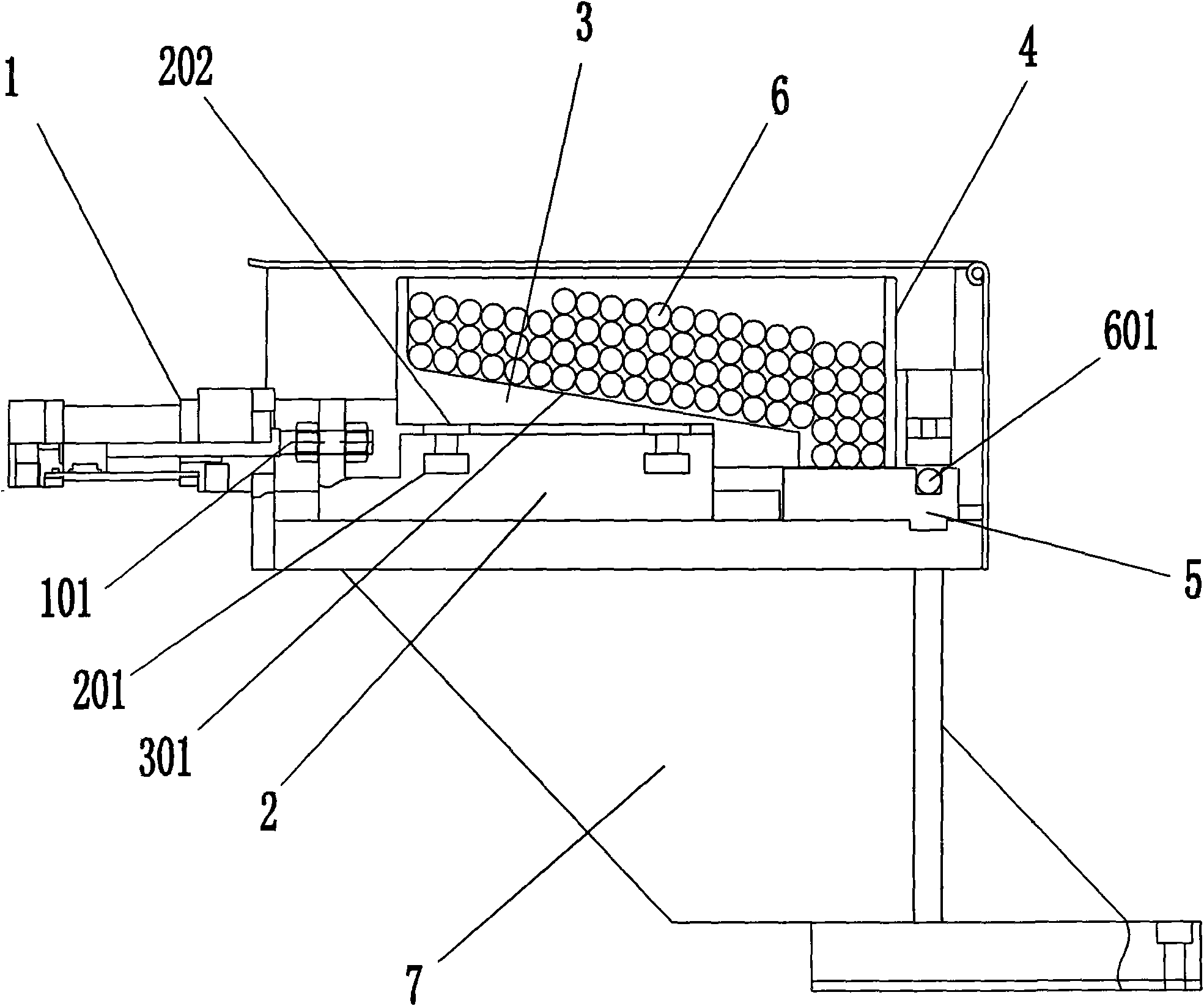
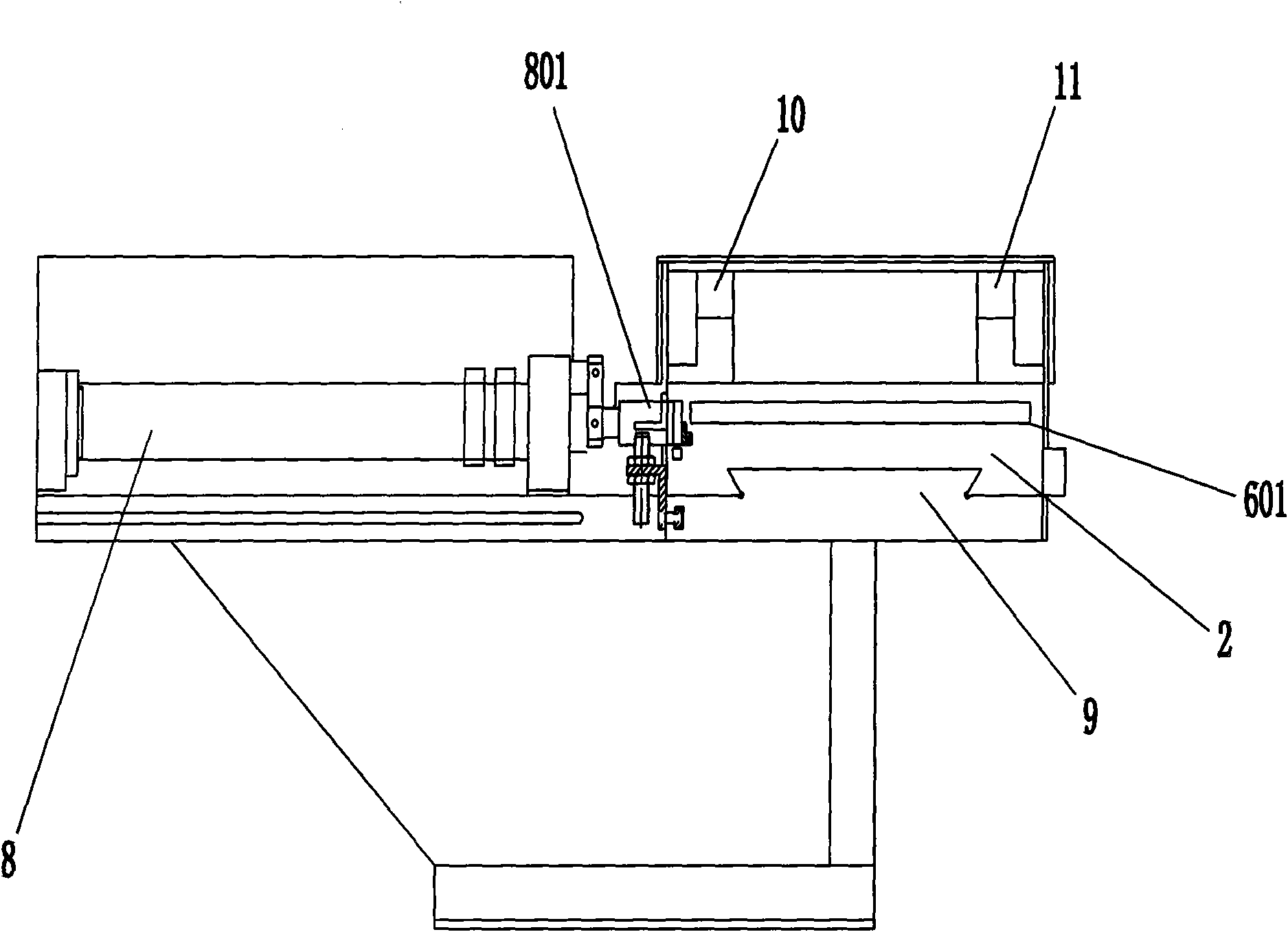
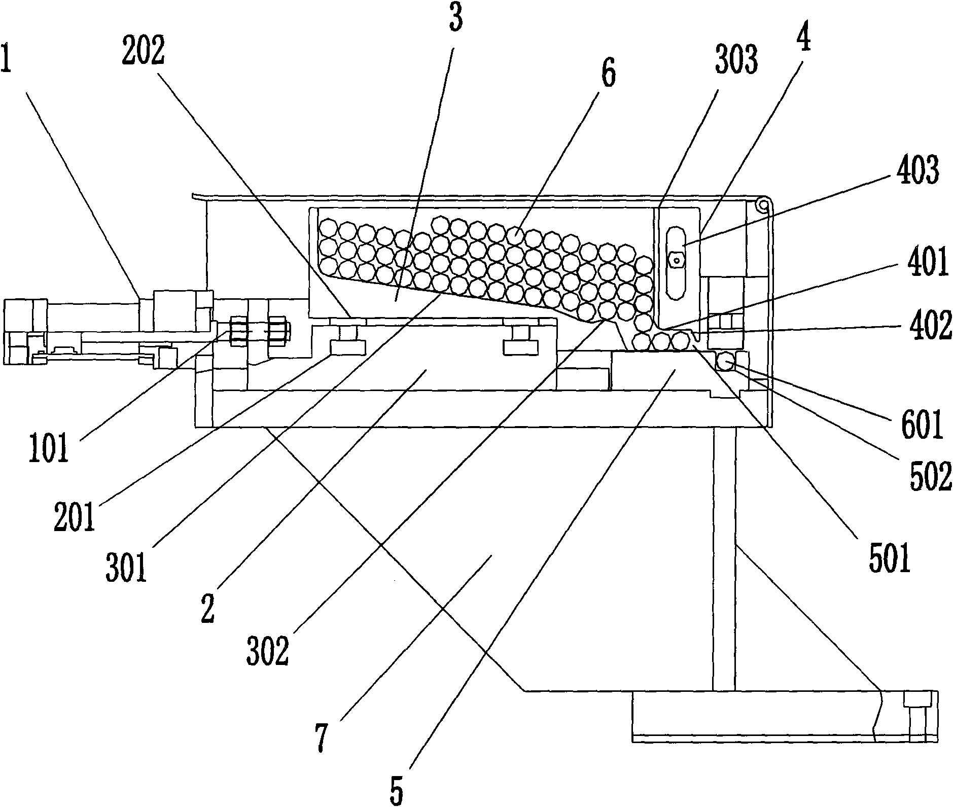
[0021] The core idea of ​​the present invention is: there is a section of buffer arc surface at the end of the bottom surface of the silo, the drill bit can be pushed down along the buffer arc surface, and the inertia and impact during the downward process of the drill bit can be effectively reduced while pushing the guide plate through The "U"-shaped groove and screws are movably fixed on the side wall of the discharge port of the silo, and there is a notch with an inclined chamfer at the lower end of the guide plate, and the inclined chamfer gradually downwards, and forms a gap with the guide block. Open slot, when the drill bit advances, it can pass through the inclined chamfered gap smoothly through the open slot, and enter the receiving slot, so that there will be no material jamming phenomenon.

[0022] In order to illustrate the idea and purpose of the present invention, the present invention will be further described in detail below in conjunction with the accompanying ...


PUM


Abstract

The invention discloses an automatic feed mechanism of a numeric-control drill tip grinder, which comprises a base, a hopper base arranged on the base and a guide block, wherein a feed bin is fixedly arranged on the hopper base, a guide board is movably fixed on the side wall of the discharge hole of the feed bin, the lower end of the guide board is provided with a gap, and an open slot is formed between the gap and the guide block. The automatic feed mechanism of the invention can effectively solve a jamming problem in feeding, and has the advantages of quick feeding, good feeding stability, high feeding efficiency, simple structure, and the like. A plurality of grinders can be simultaneously operated for production by one person, and production cost can be greatly reduced for companies.

Description

Technical field: [0001] The invention relates to a grinding forming machine tool, in particular to a novel automatic feeding mechanism of a fully automatic numerically controlled drill point grinder. Background technique: [0002] The working principle of the existing automatic feeding mechanism of the drill point grinder mainly includes two parts: pushing and feeding. Figure 1 ~ Figure 2 As shown, the working principle of material pushing is: when the material pushing cylinder 1 works, it drives the material pushing rod 101 to move forward, and the material pushing rod 101 pushes the hopper seat 2 to move forward. The dovetail groove 9 moves forward, and the feed bin 3 fixedly installed on the hopper seat 2 advances under its drive. Since the drill bit 6 is stored in the feed bin 3, the feed bin 3 drives the drill bit 6 to move forward when it advances. When the guide plate 4 moves to the material receiving groove of the guide block 5, a drill bit 601 will fall into the ma...

Claims


Application Information

Patent Timeline
Patent Type & Authority Applications(China)
IPC IPC(8): B24B3/24
Inventor 胡思节
Owner SHENZHEN GOLD DRILL TOOLS & MFR TECH
Why Eureka
Try Eureka