Method for designing sliding pair of tapered roller bearing of speed increaser of aerogenerator

A technology of tapered roller bearing and design method, applied in the direction of roller bearing, bearing element, shaft and bearing, etc., can solve the problem of sliding friction between the large end face of tapered roller and the guide rib of ferrule which has not yet been developed

Inactive Publication Date: 2009-12-02
郭溪泉
View PDF0 Cites 3 Cited by
  • Summary
  • Abstract
  • Description
  • Claims
  • Application Information

AI Technical Summary

Problems solved by technology

It can be seen that the current theoretical research on rolling bearings is only aimed at the structural status quo of tapered roller bearings, and has analyzed and calculated the elastohydrodynamic problem of the line contact between the roller and the raceway. Conduct in-depth research on the sliding friction problem of the rib and improve the design

Method used


Image

  • Method for designing sliding pair of tapered roller bearing of speed increaser of aerogenerator
  • Method for designing sliding pair of tapered roller bearing of speed increaser of aerogenerator
  • Method for designing sliding pair of tapered roller bearing of speed increaser of aerogenerator

Examples


Embodiment Construction

[0025] 1. Calculate the axial load borne by the tapered roller: first calculate the axial load caused by the radial load (due to the different contact angles of the inner and outer ring raceways of the bearing); secondly, calculate the axial load distributed by the bearing to the gear The force borne by the side (the axial load of the bearing is jointly borne by the roller-raceway contact surface and the roller-rib); again, it is the additional axial load caused by the centrifugal force of the roller and the rotation of the planetary wheel bearing around the eccentric axis ;

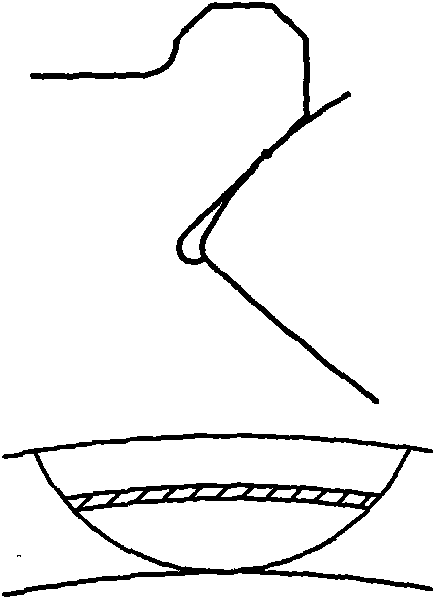
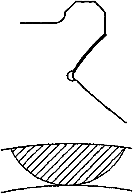
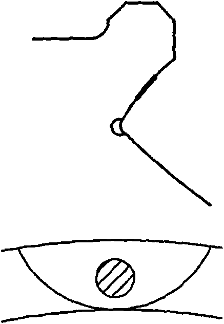
[0026] 2. Select the appropriate contact point position in the roller-rib coupling gap during design:

[0027] 3. Determine the viscosity of lubricating oil;

[0028] 4. Select the ball radius of the spherical surface of the roller end and the inner spherical surface of the rib;

[0029] 5. At the contact point, the distance between the two surfaces is determined according to the principle of 3-5 times...


PUM


Abstract

The invention discloses a method for designing a sliding pair of a tapered roller bearing of a speed increaser of an aerogenerator, which comprises the steps of: manufacturing space shapes of a large end surface of a tapered roller and the inner surface of a flange of an inner bearing ring into spherical surfaces respectively, wherein the large end surface of the tapered roller is a round part on the spherical surfaces, and the space shape of the inner surface of the flange is a spherical ring; ensuring that the spherical radius of the large end surface of the tapered roller is less than that of the spherical ring of the inner surface of the flange, wherein two spherical surfaces can form a divergent space wedge gap between two surfaces sliding relatively from a contact point, and the wedge gap is a convergent wedge gap when pointing to the contact point; selecting the spherical radius of the large end surface of the tapered roller and the spherical radius of the spherical ring of the inner surface of the flange, namely reasonably selecting the shape and size of the gap between the spherical surface of the large end surface of the tapered roller and the spherical surface of the spherical ring of the inner surface of the flange; and ensuring that during the work, the contact point of the spherical surface of the large end surface of the tapered roller and the inner surface of the flange is on a plane where a theoretical axis of the tapered roller and an axis of an inside race are positioned, and is a proper point between the upper edge of the inner surface of the flange and the edge of a grinding undercut. The method ensures that the tapered roller bearing can be ideally applied to speed increasers of aerogenerators and all equipment with high-speed operation.

Description

technical field [0001] The preferred target of the present invention is the high-speed tapered roller (including cylindrical roller) bearing in the wind power generator speed increaser, which belongs to the field of high-speed rotary mechanical transmission and involves changing the main sliding part of the tapered roller (including cylindrical roller) bearing In the friction state, a complete hydrodynamic oil film is formed between the relative sliding surfaces, and the boundary friction is changed to pure liquid friction, which solves the problem that the tapered roller bearing cannot work at high speed due to friction, wear, and heat, and meets the long-term needs of wind turbines. Life expectancy (service life of 20 years), high reliability (more than 130,000 hours of trouble-free operation, reliability of more than 95%), and high transmission efficiency requirements; it is the technical basis for the research and development of clean new energy equipment. [0002] The inv...

Claims


Application Information

Patent Timeline
IPC IPC(8): F16C19/22F16C33/36F16C33/66
Inventor 李树青郭溪泉
Owner 郭溪泉
Why Eureka
Try Eureka