
Automatic glare-shielding control method for liquid crystal sunglasses and control device thereof

A control method and technology of a control device, applied in the field of sunglasses, can solve the problems of poor practicability, difficulty in controlling discoloration, inconvenient manufacture and use, etc., and achieve the effects of small size, convenient use and simple structure

Inactive Publication Date: 2009-12-02
北京明松博来科技有限公司
View PDF0 Cites 5 Cited by
  • Summary
  • Abstract
  • Description
  • Claims
  • Application Information

AI Technical Summary

Problems solved by technology

However, the strong light source in the field of view of the human eye is dynamically changing, and the parts that need to be shaded on the lens also need to be constantly changing, which brings difficulties to control discoloration. Obscuring incoming light from an area
The control method of this kind of glasses is complicated, and its function needs to be realized through a large, heavy, and expensive electronic control device. The lens is divided into multiple areas in order to achieve local control. There are light and dark divisions on the lens. These glasses need to maintain a fixed distance between the human eye and the lens to calculate the angle of the incident strong light.
This will inevitably complicate the control circuit and increase the volume of the control system, making it inconvenient to manufacture and use.

Method used


Image

  • Automatic glare-shielding control method for liquid crystal sunglasses and control device thereof
  • Automatic glare-shielding control method for liquid crystal sunglasses and control device thereof
  • Automatic glare-shielding control method for liquid crystal sunglasses and control device thereof

Examples


Embodiment Construction

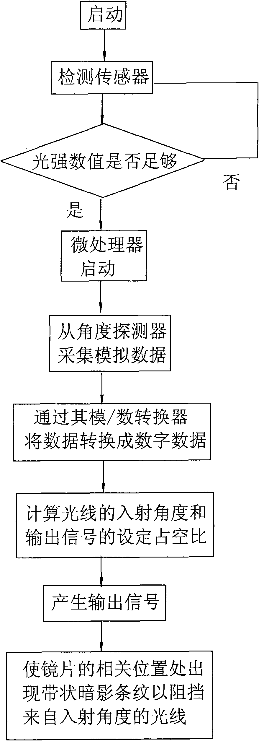
[0025] see figure 1 Schematic diagram of the structure of this example.

[0026] There is a liquid crystal lens with a layer of transparent conductive film on both sides to form electrodes, the two electrodes are electrically connected to the control output end of the controller, and the input end of the controller is connected with a light intensity sensor and a light angle sensor.

[0027] The controller is a digitally integrated CPU chip, which is welded on a printed circuit board and electrically connected to other components through the printed circuit board.

[0028] The solar cell supplies power to the CPU chip, the angle sensor and the light sensor through the printed circuit board.

[0029] The CPU chip uses the product of Texas Instruments, the model is MSP430F2012, and this CPU chip already contains an analog-to-digital converter. There are many other CPU chips that can be used as suitable substitutes, and microcontrollers that already contain operational amplifie...


PUM


Abstract

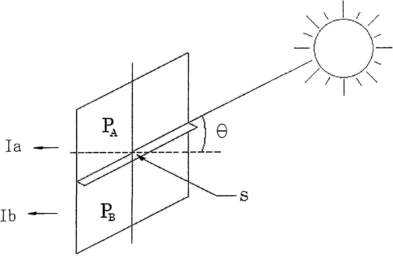
The invention relates to an automatic glare-shielding control method for liquid crystal sunglasses and a control device thereof. The control method comprises the following steps: liquid crystal lens are arranged on the sunglasses, and conductive film electrodes and controllers are arranged on both sides of the liquid crystal lens; the output ends of the controllers are connected with a light angle sensor and an illuminance sensor, when illuminance is less than a set threshold value, the voltage output is controlled by the controllers with no dark band; when illuminance is larger than the set threshold value, dark band control voltage is output by the controllers according to the angle of a light source to the liquid crystal lens; according to the characteristics that when the voltage rises to a certain value, a dark band is seen above a lens and the dark band can move down with the increase of the voltage, dark bands seen by human eyes are moved to shield the position of the light source by the controllers which use the dark band control voltage, and the dark band control voltage is higher than the upper limit of the critical value of the control voltage in homogeneous transmittance sensitive control region of the lens. The invention can realize the function of automatic shielding dynamic glare in a certain direction on non-division lens and has the advantages of simple structure and small volume.

Description

technical field [0001] The invention relates to a pair of sunglasses, in particular to a control method and a control device for automatically blocking strong light for liquid crystal sunglasses. Background technique [0002] The light transmittance of liquid crystal is related to the voltage applied to it, and it has the following photoelectric characteristics: when the voltage is lower than the lower limit critical value, its light transmittance changes slowly and is insensitive; when the control voltage is higher than the lower limit critical value When the voltage is lower than the upper critical value, the uniform light transmittance of the liquid crystal will sensitively decrease with the increase of the voltage, forming a sensitive control area of ​​uniform light transmittance. When the voltage is higher than the upper limit critical voltage, the light transmittance will not increase It changes with the increase of voltage, so when people use voltage to control the li...

Claims


Application Information

Patent Timeline
Patent Type & Authority Applications(China)
IPC IPC(8): G02C7/10G02F1/133G09G3/36
Inventor 陈明彻
Owner 北京明松博来科技有限公司
Learn More