Hydraulic control circuit for construction machine

A technology of oil pressure control and construction machinery, applied in mechanical equipment, construction, servo meter circuits, etc., can solve problems such as poor workability and achieve good workability

Inactive Publication Date: 2012-05-23
CATEPILLAR SARL
View PDF5 Cites 0 Cited by
  • Summary
  • Abstract
  • Description
  • Claims
  • Application Information

AI Technical Summary

Problems solved by technology

Therefore, even if the operator sets the target rotational speed with the engine rotational speed setting tool in consideration of the working speed, the content of the work, etc., the downward movement speed of the boom does not change, but there is a problem of poor workability, which is the problem to be solved by the present invention.

Method used


Image

  • Hydraulic control circuit for construction machine
  • Hydraulic control circuit for construction machine
  • Hydraulic control circuit for construction machine

Examples


Embodiment Construction

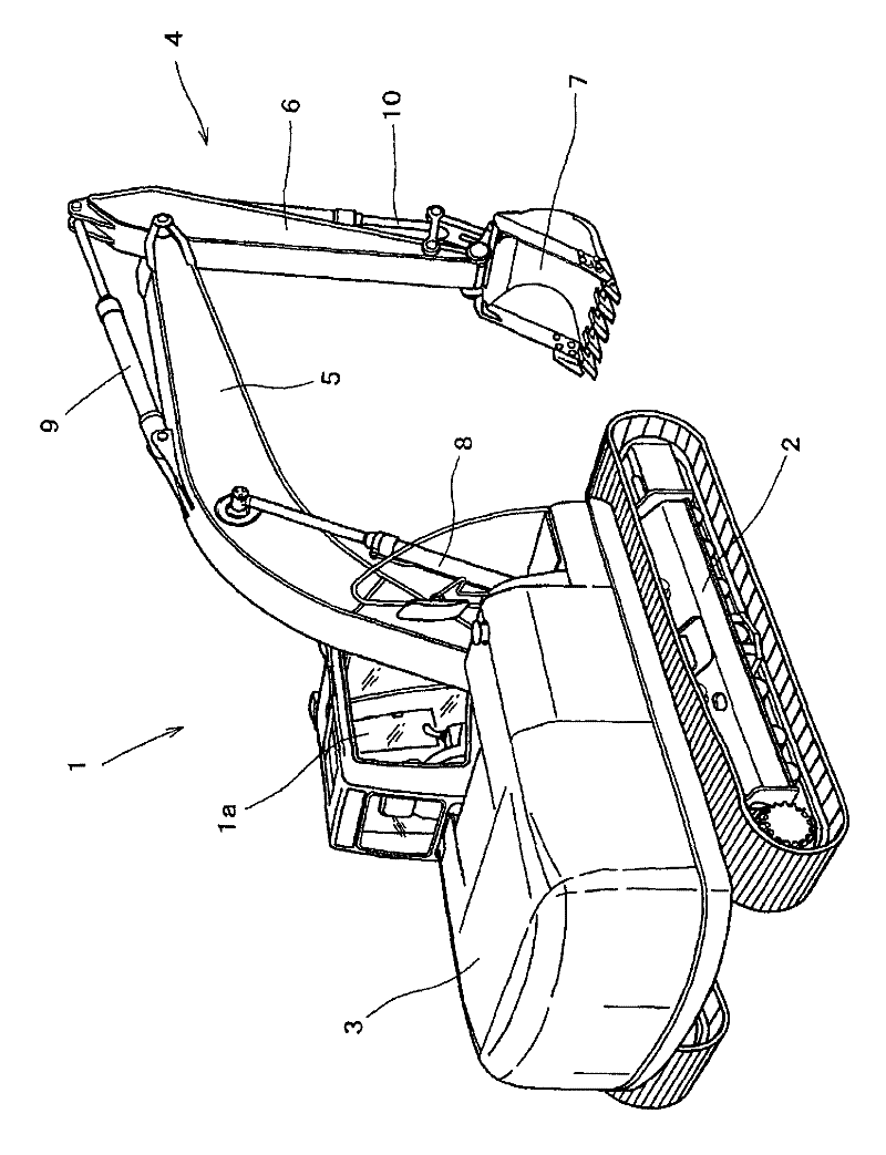
[0033] Next, according to Figure 1 ~ Figure 3 The first embodiment of the present invention will be described. in figure 1 Among them, 1 is a hydraulic excavator. The hydraulic excavator 1 includes: a crawler-type lower running body 2; an upper rotating body 3 rotatably supported on the lower running body 2; and an upper rotating body 3 mounted on it The front working machine 4, etc., and the front working machine 4 includes: a cantilever 5 supported on the upper rotating body 3 movably at its base end; an operating lever 6 supported at the front end of the cantilever 5 freely swinging back and forth; The bucket 7 and other parts attached to the front end of the operating lever 6 are provided with left and right traveling motors, rotating motors, boom cylinders 8, operating lever cylinders 9, and bucket cylinders 10 (not shown). The basic structure of the hydraulic actuator is the same as before. In addition, in figure 1 Among them, 1a is the space of the operator's cab.

[0...


PUM


Abstract

A hydraulic control loop has a hydraulic cylinder for vertically moving a heavy object, a hydraulic pump driven by an engine as a drive source to supply hydraulic pressure to the hydraulic cylinder, a recovery oil passage which, when the heavy object is lowered, feeds oil discharged from a weight holding-side oil chamber to the oil chamber on the side opposite the weight holding side, and an engine speed setting device. The hydraulic control circuit is adapted to improve fuel consumption and to match lowering speed of the heavy object to a value set by the engine speed setting device. A recovery control valve (13), whose degree of opening is regulated according to a control command from a control device (18), is placed in a recovery oil passage (C). The control device (18) performs engine speed reduction control which, when a boom is lowered, reduces the speed of the engine (E) to or below an engine speed for reduction control, and the control device also performs recovery amount regulating control for increasing or decreasing the degree of opening of the recovery control valve (13) according to a preset target speed set by an accelerator dial (20).

Description

Technical field [0001] The present invention relates to the technical field of a hydraulic control circuit in a construction machine equipped with a hydraulic cylinder for moving heavy cargo up and down. Background technique [0002] Generally, in construction machinery such as hydraulic excavators, various hydraulic actuators such as hydraulic cylinders for moving heavy cargo up and down are installed, and the oil is supplied and discharged to these hydraulic actuators according to the operation of the operating equipment. When the hydraulic actuator is a boom cylinder used to move the boom of a hydraulic excavator up and down, a hydraulic pump that becomes a hydraulic supply source, etc., the boom The cylinder is configured to move the cantilever upward by supplying oil to the head-side oil chamber as the weight holding side oil chamber and oil discharge from the rod-side oil chamber as the anti-weight holding side oil chamber. The oil supply from the oil chamber and the oil d...

Claims


Application Information

Patent Timeline
Patent Type & Authority Patents(China)
IPC IPC(8): F15B11/024E02F9/22
CPCE02F9/2285F15B2211/7053E02F9/2292F15B2211/633F15B21/14E02F9/2296F15B2211/6316F15B2211/3122F15B2211/329F15B2211/20576F15B2211/3116F15B2211/88E02F9/2228F15B2211/761F15B2211/6355E02F9/2217
Inventor 岛田佳幸西川裕康三岛贤横山裕
Owner CATEPILLAR SARL
Why Eureka
Try Eureka