Receptacle optical module and method for manufacturing the same

A manufacturing method and technology of optical modules, applied in optics, light guides, lasers, etc., can solve the problem that the laser beam profile is not a perfect circle, etc.

Inactive Publication Date: 2009-12-02
SUMITOMO ELECTRIC IND LTD
View PDF2 Cites 10 Cited by
  • Summary
  • Abstract
  • Description
  • Claims
  • Application Information

AI Technical Summary

Problems solved by technology

However, the profile of the laser beam is not a perfect circle because the fiber end is not in the optimal position

Method used


Image

  • Receptacle optical module and method for manufacturing the same
  • Receptacle optical module and method for manufacturing the same
  • Receptacle optical module and method for manufacturing the same

Examples


Embodiment 1

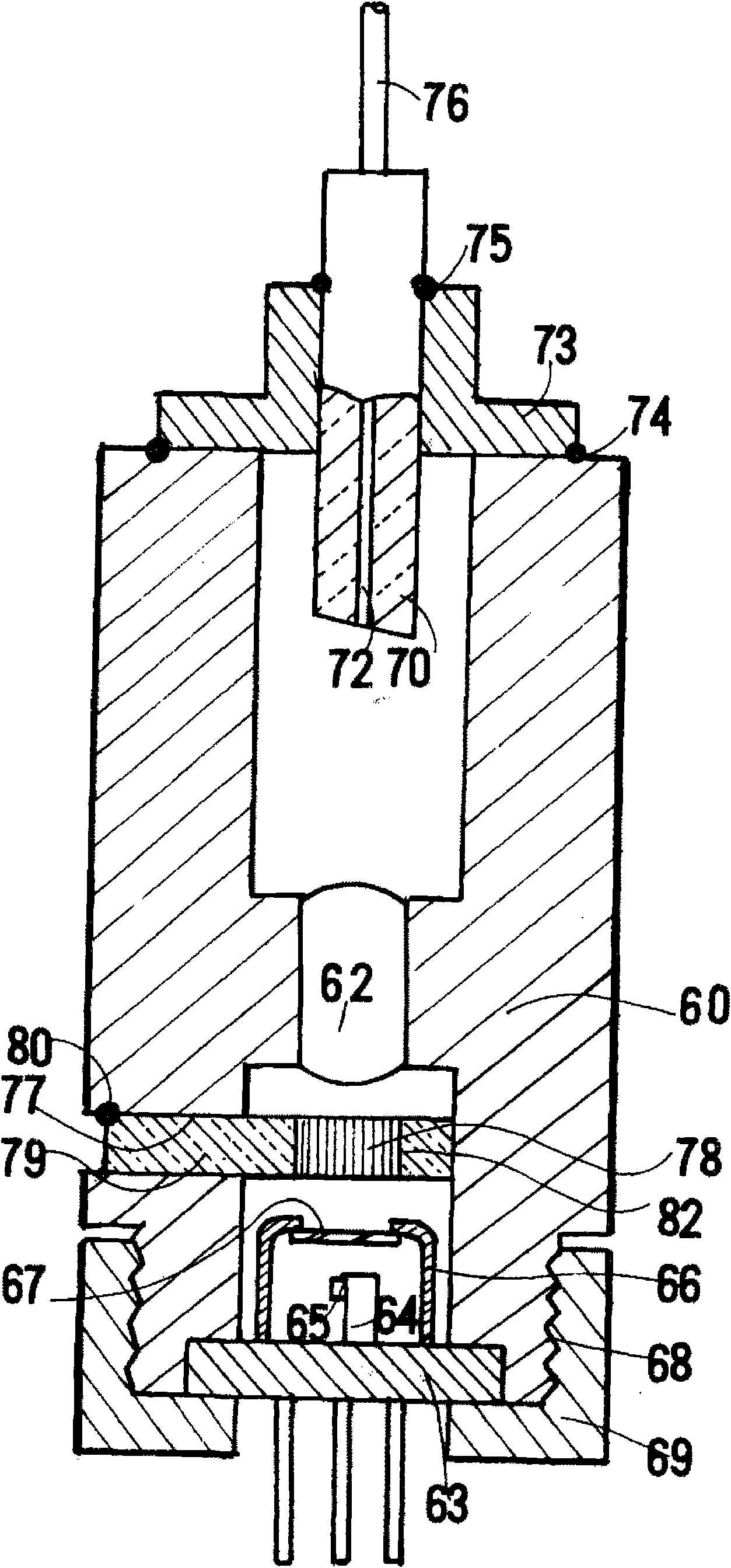
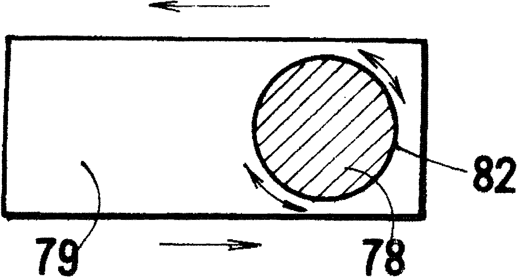
[0100] In the present invention, between the light-emitting light-concentrating part including the light-emitting element chip (LD) and the lens, and the socket part including the fiber stub (Fiber stub) and detachably holding the external optical fiber, a rotationally symmetrical shape is provided and maintained. Optical elements with polarization properties on the joint sleeve. First, adjust the positional relationship between the light-emitting concentrating system and the optical fiber ferrule to the quasi-optimum position (the point with the largest amount of light in the XY and R directions, and point G on the extension line of the concentrating point H in the Z direction). The rotation angle of the optical element with polarization characteristics that enables the external optical fiber to obtain a desired amount of light is obtained by rotating the splice sleeve and the optical element with polarization characteristics integrally. And, at this angle, the joint sleeve, ...

Embodiment 2

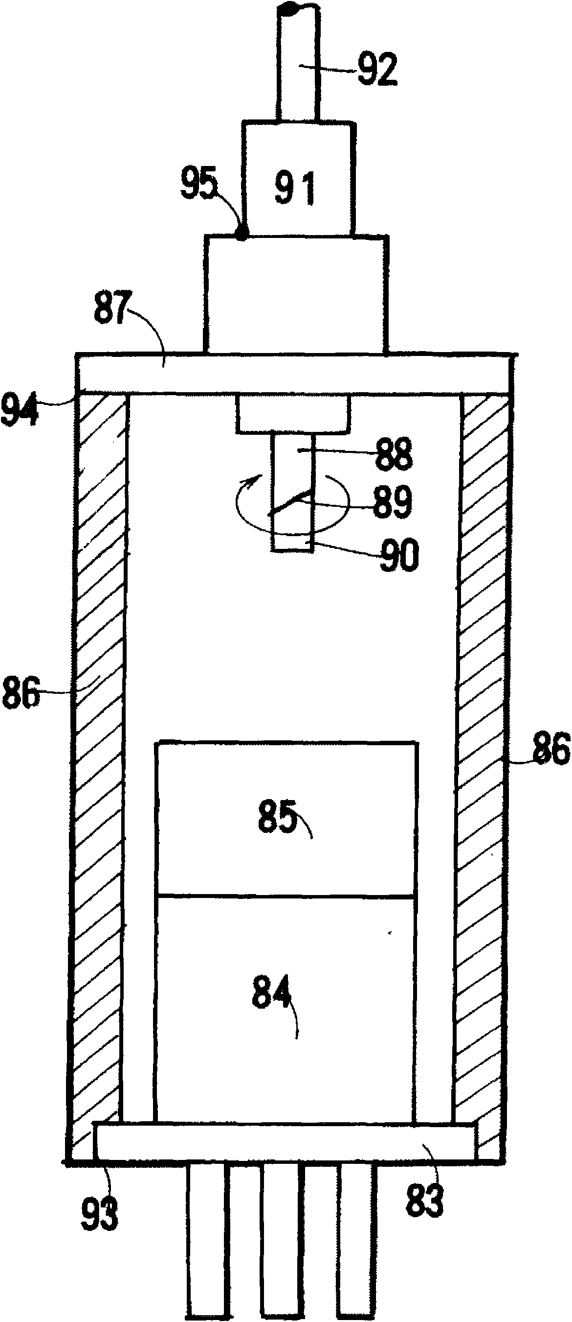
[0138] In the present invention, a splice sleeve held in a rotationally symmetrical shape is provided between the light-emitting converging section including the light-emitting element chip (LD) and the lens, and the socket section including the fiber ferrule and detachably holding the external optical fiber. Optical elements with polarization properties. Adjust the positional relationship between the light-emitting concentrating system and the optical fiber ferrule to the quasi-optimum position (the point with the largest amount of light in the XY and R directions, and the G point on the extension line of the concentrating point H in the Z direction). The rotation angle of the optical element with polarization characteristics that enables the external optical fiber to obtain a desired amount of light is obtained by rotating the splice sleeve and the optical element with polarization characteristics integrally. Under this angle, the joint sleeve, the light-emitting concentrati...


PUM

PropertyMeasurementUnit
Lengthaaaaaaaaaa

Abstract

Provided is a receptacle type LD module having few irregularities of output power between external optical fibers and few fluctuations of output power caused by a temperature change or a time elapse even when different external light fibers are detachably attached. An optical element (4) having polarization characteristic held on a rotationally symmetric joint sleeve (5) is arranged between a light emission / light collection unit formed by a light emitting element chip (LD) (2) and a lens (3), and a receptacle (9) which has a fiber stub (44) and detachably holds an external optical fiber. The positional relationship between the light emission / light collection unit and the fiber stub (44) is appropriately adjusted. The joint sleeve (5) and the optical element (4) having polarization characteristic are rotated as a unitary block so as to obtain a rotation angle (theta c or theta d) at which a desired light amount (Ec or Ed) to the external optical fibers can be obtained. At the angle, the joint sleeve (5), the light emission / light collection unit, and the receptacle (9) are welded together.

Description

technical field [0001] There are two types of semiconductor laser (LD) modules: tap type (Pigtail type) and socket type (Receptacle type). The receptacle type allows the ferrule of the external fiber to be inserted directly relative to the receptacle. The invention relates to a socket-type semiconductor laser (LD) module, which can plug and unplug external optical fibers, and the output deviation between different external optical fibers is small. Even if there is a change in temperature or external stress, the external optical fiber can always Output the desired amount of light. Background technique [0002] Semiconductor Laser Module (LD) The module consists of a semiconductor laser (LD), a lens, and the end of an optical fiber. The shorter fiber remains in the ferrule but is connected to the ferrule of the outer fiber and thus temporarily connected to the ferrule fiber. [0003] Alignment (adjustment) refers to the operation of obtaining an appropriate positional relat...

Claims


Application Information

Patent Timeline
IPC IPC(8): G02B6/42H01S5/022
CPCH01S5/0683H01S5/02296G02B6/4206G02B6/4204H01S5/02284H01L2224/48091H01S5/02251H01S5/02257H01L2924/00014
Inventor 若崎环树冈田毅
Owner SUMITOMO ELECTRIC IND LTD
Why Eureka
Try Eureka