

Deep layer section soil sampler and sampling method thereof
A soil sampler and sampler technology, applied in the direction of sampling devices, etc., can solve the problems of large destructiveness, soil layer cracking, compaction, compaction, disturbing soil, etc., and achieve the effect of easy separation, non-deformation, and simple operation
- Summary
- Abstract
- Description
- Claims
- Application Information
AI Technical Summary
Problems solved by technology
Method used
Image

Examples
Embodiment Construction
[0036] The technical scheme of the present invention is described in detail below in conjunction with accompanying drawing:
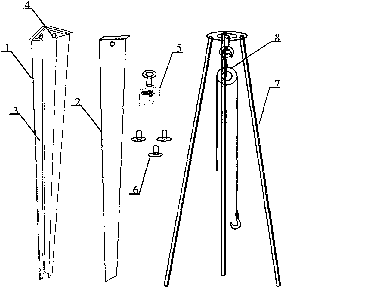
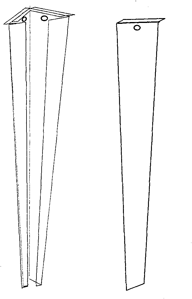
[0037] Such as figure 1 Shown, the present invention comprises the main sampler 1 that is inverted triangular conical shape, seal piece 2, fixer 5, tripod 7, the cross section of main sampler 1 is equilateral right triangle, and main sampler 1 is arranged longitudinally along hypotenuse The opening 3, the sealing piece 2 matches the longitudinal opening 3, the upper ends of the main sampler 1 and the sealing piece 2 are respectively provided with extensions, and the main sampler 1 is provided with connecting circular holes 4 horizontally on two adjacent right-angled side walls respectively, The side wall of the sealing sheet 2 is provided with a connection hole corresponding to the above-mentioned connecting round hole 4; the fixer 5 is arranged inside the upper end of the main sampler 1, and the fixing device 5 is respectively connected to the main sam...
PUM
| Property | Measurement | Unit |
|---|---|---|
| Length | aaaaa | aaaaa |
Abstract
Description
Claims
Application Information