
Rail-straightening machine

A technology for straightening machines and rails, applied in other manufacturing equipment/tools, metal rolling, manufacturing tools, etc., can solve problems such as no solution, production waste, etc., and achieve the effect of reducing rail height and eliminating rail height differences

Inactive Publication Date: 2009-12-16
PANGANG GROUP VANADIUM TITANIUM & RESOURCES
View PDF0 Cites 8 Cited by
  • Summary
  • Abstract
  • Description
  • Claims
  • Application Information

AI Technical Summary

Problems solved by technology

[0003] To sum up, the problem of blind straightening of rails has brought about serious production waste. Although this problem has always existed, there has never been an effective solution

Method used


Image

  • Rail-straightening machine

Examples


Embodiment 1

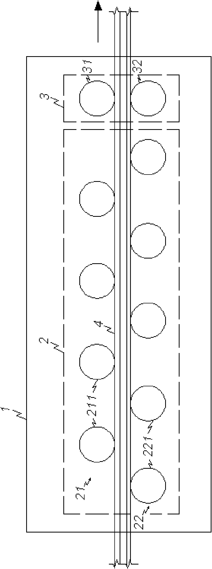
[0017] The rail straightening machine of the present invention is used to carry out the straightening test on the 60 heavy rails made of U75V. The diameter selection requirements of the cold rolls 31 and 32 at the output end of the straightening roll system 2 in the straightening machine are consistent, all being 400-600 mm, the motor power is 500KW, the rotational speed requirements of the cold rolls 31 and 32 are consistent, and the roll materials are all high chromium alloy cast iron. The roll gap reduction between cold rolls 31 and 32 is hydraulic pressure, and the reduction value is 2 mm. After cold rolling, the specification and size of the straightening blind zone and the flatness of the end reach the level of the straightening zone, and then samples are sent for testing. The residual stress is 186Mpa, which is less than the standard 250Mpa of high-speed railway rails, and the fracture toughness is K 1C The single minimum value is 32Mpa.m 1 / 2 , greater than the 26Mpa.m...

Embodiment 2

[0019] Adopt rail straightening machine of the present invention to carry out straightening test to the 60 heavy rails that the material after straightening is U71Mn, be positioned at the diameter selection requirement of the cold rolling roll 31,32 of straightening roller system 2 output ends in this straightening machine, be consistent, be 400-600 mm, the motor power is 500KW, the rotational speed requirements of the cold rolls 31 and 32 are consistent, and the rolls are made of high chromium alloy cast iron. The roll gap reduction between cold rolls 31 and 32 is hydraulic pressure, and the reduction value is 2 mm. After cold rolling, the specification and size of the straightening blind zone and the flatness of the end reach the level of the straightening zone, and then samples are sent for testing. The residual stress is 178Mpa, which is less than the standard 250Mpa of high-speed railway rails, and the fracture toughness is K 1C The single minimum value is 37Mpa.m 1 / 2 , ...


PUM

PropertyMeasurementUnit
diameteraaaaaaaaaa

Abstract

The invention discloses a novel rail-straightening machine capable of effectively improving a straightening dead zone of a rail, and avoids waste caused by cutting off the straightening dead zone. The straightening machine comprises a straightener roll system and a cold roll system, wherein the straightener roll system is arranged on a frame; the cold roll system is positioned at the output end of the straightener roll system on the frame and consists of at least one pair of cold rolls with line of centers vertical to the running direction of the rail; and roll gaps which can be passed through by the rail are alternately formed among the cold rolls. The rail-straightening machine creatively adds cold rolling equipment onto the prior rail-straightening machine so as to form the novel rail-straightening machine, and carries out cold rolling on the rail which is straightened by the straightener roll system through the at least one pair of the cold rolls with the line of centers vertical to the running direction of the rail in the cold rolling equipment, thereby reducing rail height of the straightening dead zone of the rail, effectively improving even eliminating the difference of rail heights of the straightening dead zone of the rail and the straightening zone of the rail, and playing a role in correcting full-length fluctuation of the rail height of the rail.

Description

technical field [0001] The invention relates to a rail straightening machine. Background technique [0002] After the rail is rolled and formed, it needs to be straightened. The existing rail straightening machine comprises a straightening roll system consisting of an upper straightening roll set and a lower straightening roll set, the upper straightening roll in the upper straightening roll set and the lower straightening roll in the lower straightening roll set The straightening rollers are arranged staggered along the running direction of the rail. Since the upper straightening rollers and the lower straightening rollers are alternately arranged, when the rail passes through the straightening roller system, the two ends of the rail cannot be balanced at three points, so there is always a straightening dead zone at the two ends of the rail after straightening. The straightening blind zone of the rail is 0.4-0.6 mm higher than the rail straightening area, the rail waist i...

Claims


Application Information

Patent Timeline
Patent Type & Authority Applications(China)
IPC IPC(8): B23P23/02B21D3/05B21B1/085B21B27/02
Inventor 陶功明唐历李光跃李春平蒲学坤贾济海
Owner PANGANG GROUP VANADIUM TITANIUM & RESOURCES
Learn More