Array substrate for liquid crystal display device

A liquid crystal display and array substrate technology, applied in the field of array substrates, can solve the problems of reducing product yield, inducing static electricity, and failing to obtain TFT operations.

Active Publication Date: 2009-12-16
LG DISPLAY CO LTD
View PDF0 Cites 41 Cited by
  • Summary
  • Abstract
  • Description
  • Claims
  • Application Information

AI Technical Summary

Problems solved by technology

However, in the step of forming electrodes and wirings on the array substrate 10, due to particles or pulse-shaped currents in the processing chamber, there may be induced Static electricity
[0012] Since static electric...

Method used


Image

  • Array substrate for liquid crystal display device
  • Array substrate for liquid crystal display device
  • Array substrate for liquid crystal display device

Examples


Embodiment Construction

[0025] Preferred embodiments and examples depicted in the accompanying drawings will now be discussed in detail.

[0026] In the present invention, a plurality of test pads for testing the amplitude or / and waveform of the scan signal, the data signal and the common voltage are connected to the plurality of electrostatic protection units.

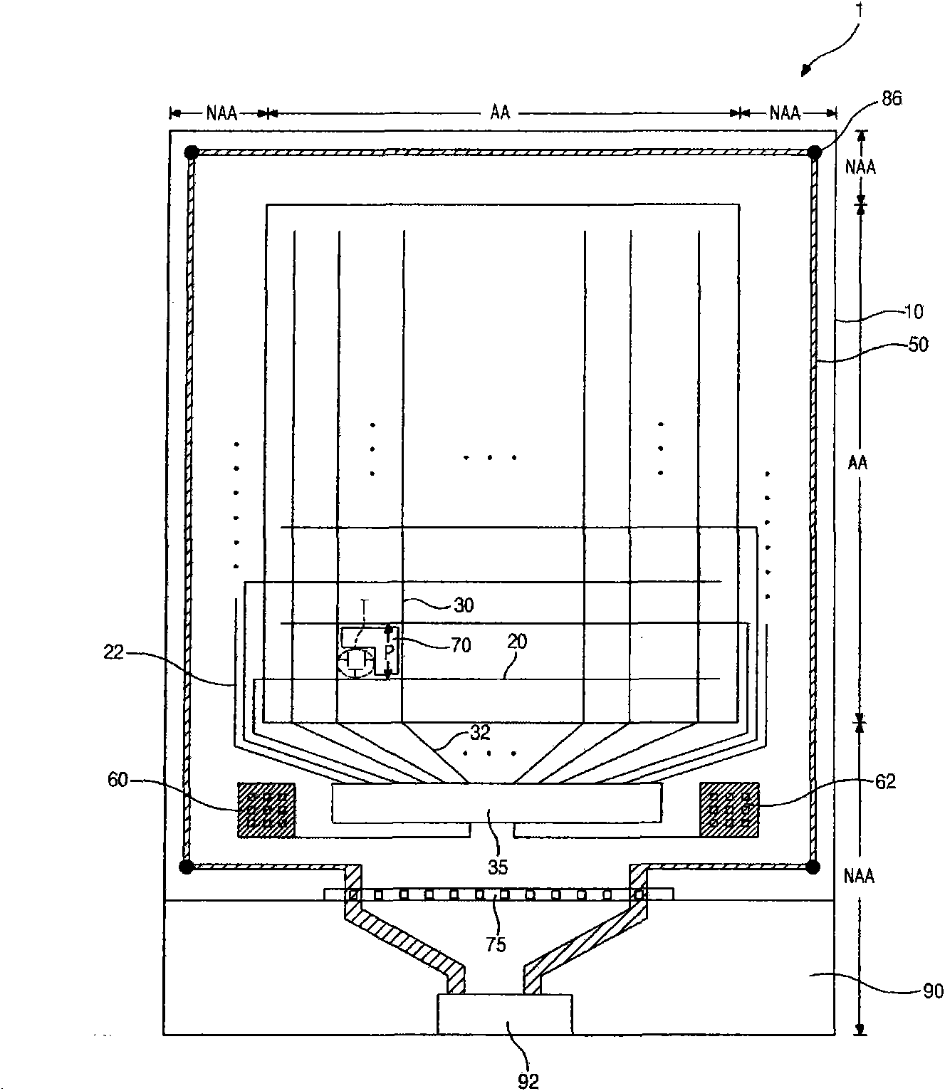
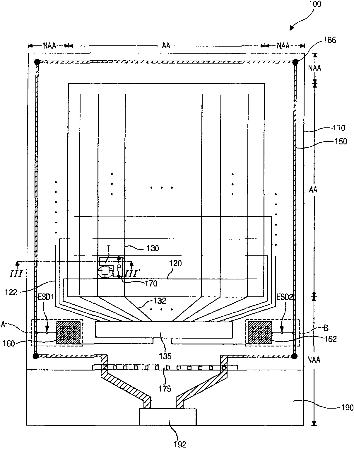
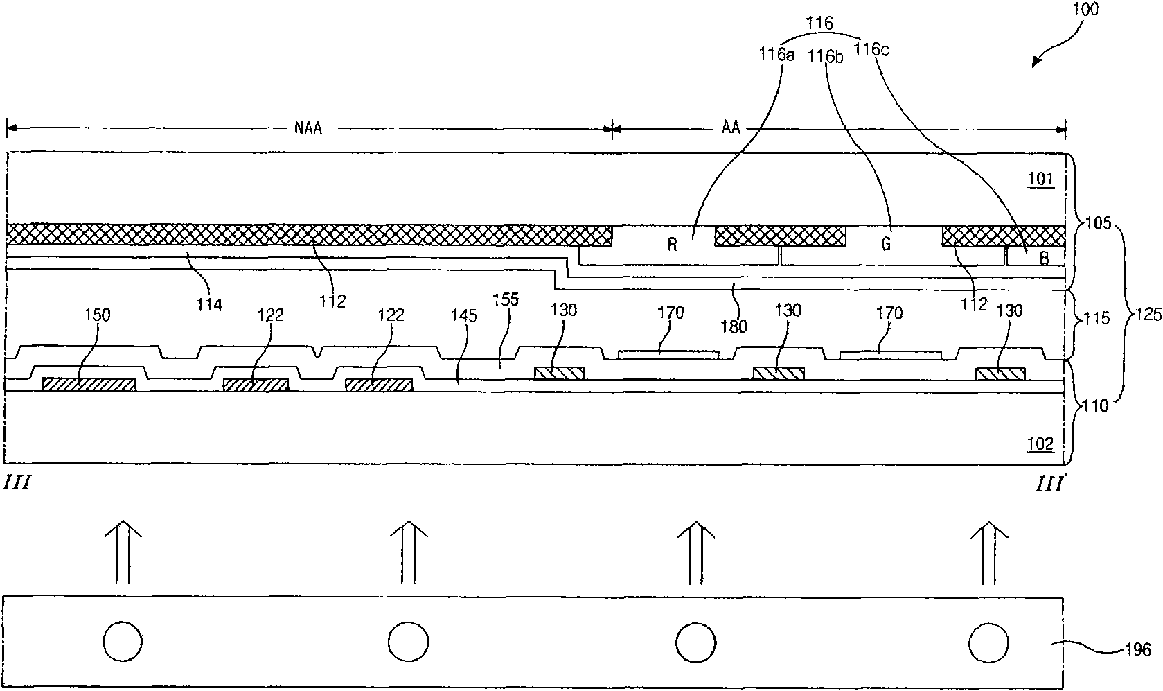
[0027] figure 2 is a schematic plan view showing an LCD device according to the present invention, image 3 It is a cross-sectional view of a portion along the line III-III'. exist figure 2 and image 3 Among them, the LCD device according to the present invention includes a color filter substrate 105, an array substrate 110 and a liquid crystal layer 115 therebetween. A display area AA for displaying an image and a non-display area (NAA) around the display area AA are defined on each of the color filter substrate 105 and the array substrate 110 . A backlight unit 196 for projecting light onto the array substrate 110 is disposed under...


PUM


Abstract

An array substrate for a liquid crystal display device includes a substrate having a display region and a non-display region at a periphery of the display region; a gate line, a data line, a thin film transistor and a pixel electrode on the substrate and in the display region; a drive integrated circuit on the substrate and in the non-display region; first and second test pads at both sides of the drive integrated circuit, respectively; a common voltage line on the substrate and along edges of the non-display region; and first and second static electricity protecting units on the substrate and in the display region, the first static electricity protecting unit connecting the first test pad with the common voltage line, and the second static electricity protecting unit connecting the second test pad with the common voltage line.

Description

[0001] This application claims priority from Korean Patent Application 2008-0055901 filed in Korea on Jun. 13, 2008, which is hereby incorporated by reference. technical field [0002] The invention relates to an array substrate of a liquid crystal display (LCD) device, in particular to an array substrate of an LCD device capable of preventing electrostatic damage. Background technique [0003] One prior art liquid crystal display (LCD) device utilizes the optical anisotropy and polarization properties of liquid crystal molecules. The liquid crystal molecules have a definite alignment direction due to the elongated shape. The alignment direction of the liquid crystal molecules can be controlled by applying an electric field across the liquid crystal molecules. In other words, when the strength and direction of the electric field are changed, the alignment of the liquid crystal molecules is also changed. Since incident light is refracted based on the orientation of the liqu...

Claims


Application Information

Patent Timeline
IPC IPC(8): G02F1/1362G02F1/133H01L27/12H05F1/02
CPCG02F1/136204G02F1/1345G02F1/13454G02F1/13
Inventor 金炳究
Owner LG DISPLAY CO LTD
Why Eureka
Try Eureka