
Manufacturing method and finished product of micro-fuse

A manufacturing method and technology of fuses, which are applied in fuse manufacturing, emergency protection devices, electrical components, etc., can solve the problems of waste material production defect rate, incomplete protection, equipment damage, etc., to achieve good product stability and provide security. , The effect of protecting circuit safety

Inactive Publication Date: 2009-12-16
邱鸿智
View PDF0 Cites 7 Cited by
  • Summary
  • Abstract
  • Description
  • Claims
  • Application Information

AI Technical Summary

Problems solved by technology

[0006] 1. The micro-fuse in the prior art has no good positioning design, poor product stability, difficult manufacturing and high cost, use of waste materials and high production defect rate
[0007] 2. The micro-fuse in the prior art, when processing the solder joints of the pins, is likely to generate local high temperature and cause secondary welding, the protection is not complete, and it cannot meet the needs of the market
[0008] 3. The micro-fuse in the prior art cannot determine the normal rated maximum current when used to protect the safety of the circuit, and cause expensive equipment to be damaged, burned, injured or dangerous accidents
[0009] 4. In the prior art, when tiny peeling occurs, it is not easy to detect the internal defect due to the normal appearance

Method used


Image

  • Manufacturing method and finished product of micro-fuse
  • Manufacturing method and finished product of micro-fuse
  • Manufacturing method and finished product of micro-fuse

Examples


Embodiment Construction

[0035] The above and other features and advantages of the present invention will be described in detail below with reference to the accompanying drawings.

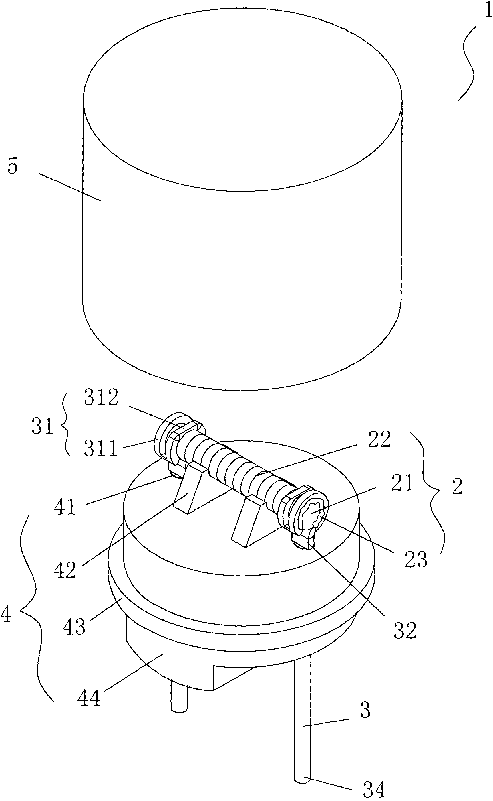
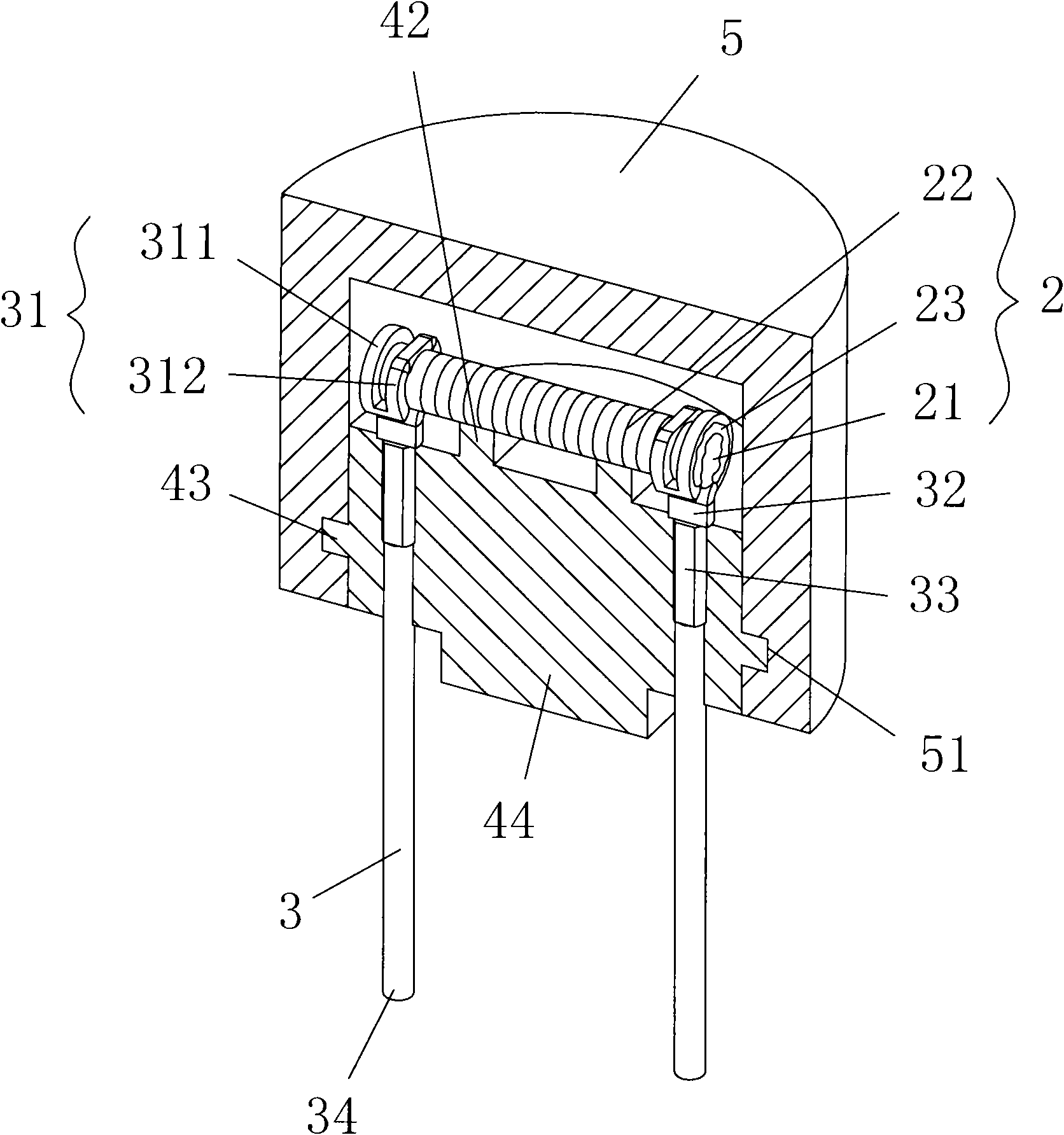
[0036] See first figure 1 and figure 2 As shown, it is respectively the three-dimensional combination schematic diagram of the appearance of the present invention and the three-dimensional schematic diagram of the partial section of the present invention; wherein a kind of miniature fuse 1 of the present invention is characterized in that it includes:

[0037] A smelting section 2 is provided with a cylinder 21 and a smelting filament 22 surrounding it, and two electrode sections are fixed at both ends;

[0038] Two electrode parts 3, one end of each electrode part 3 is vertically provided with two rings 31 with closed ends, the inner rings 311 of the two rings 31 are pressed and fixed on the inner side of the smelting part 2, the two rings 31 The outer ring body 312 is welded and fixed to the end of the smelting part 2...


PUM


Abstract

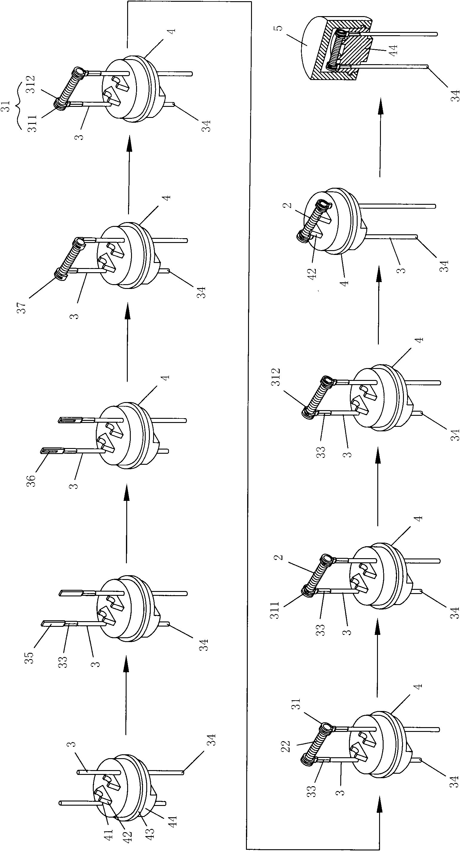
The invention relates to a micro-fuse which comprises a melting part, two electrode parts, a seat body and a cover body, wherein the melting part is provided with a column body surrounding a melting wire body to form a surrounding melting wire; one end of the electrode parts is provided with two ring bodies with closed end parts and bearing and fixing surfaces; the seat body is provided with through holes for the two electrode parts to pass through, the upper end of the seat body is provided with a bearing platform, sides of the seat body are provided with buckling rings, the lower end of the seat body is provided with a positioning block; and the cover body is buckled on the seat body to form a close space. The invention also relates to a fabricating method of the micro-fuse, which comprises the following steps: providing the seat body, arranging the two electrode parts in a penetrating way; forming planes and the bearing and fixing surfaces at the end parts of the two electrode parts, and bending through hole grooves to form the two ring bodies, wherein the inner ring body is pressed and fixedly connected to the inner side of the melting part, the outer ring body is welded and fixedly connected to the end part of the melting part; bearing the melting part by the bearing platform at the upper end of the seat body; and forming the close space by the cover body correspondingly covering the seat body. The micro-fuse has high yield, high quality and high safety.

Description

technical field [0001] The invention provides a method for manufacturing a miniature fuse and the finished product, especially related to the electrode part of the finished product, one end of which is set as a two-ring body with closed ends, and is provided with a supporting surface; in addition, the manufacturing method includes: , to form through-hole groove ends connected at the ends, so that the fusion welding can be more effective and stable. Background technique [0002] Traditional fuses are generally used in electronic products. When the current passing through the fuse is too large, the melting part will be blown to avoid dangers such as overheating and ignition of the circuit. The purpose is to protect people and equipment from damage due to overcurrent, or even fire. [0003] Furthermore, as electrical equipment is thinner and smaller, its functions are becoming more and more complex, more and more parts are required, and the circuits and electronic components on...

Claims


Application Information

Patent Timeline
IPC IPC(8): H01H85/05H01H85/143H01H69/02
Inventor 邱鸿智
Owner 邱鸿智
Learn More