Lead-acid battery grid
A technology of lead-acid batteries and grids, which is applied in the direction of electrode carriers/collectors, etc., can solve the problems of low utilization rate of active materials, small contact area between grids and active materials, etc., and achieve controllable alloy composition, good mechanical properties, The effect of capacity improvement
Inactive Publication Date: 2009-12-16
张天任
View PDF0 Cites 5 Cited by
- Summary
- Abstract
- Description
- Claims
- Application Information
AI Technical Summary
Problems solved by technology
The contact area between the grid and the active material is small, and the utilization rate of the active material is low
Method used
View moreImage
Smart ImageViewing Examples


Examples
Embodiment Construction
[0017] like figure 1 As shown, the grid of the present invention is a plate made of lead-based foam. Its surface is an irregular concave-convex surface, and its section in any direction is an irregular concave-convex surface (the plate is densely covered with honeycomb small pores).
Login to View More PUM
 Abstract
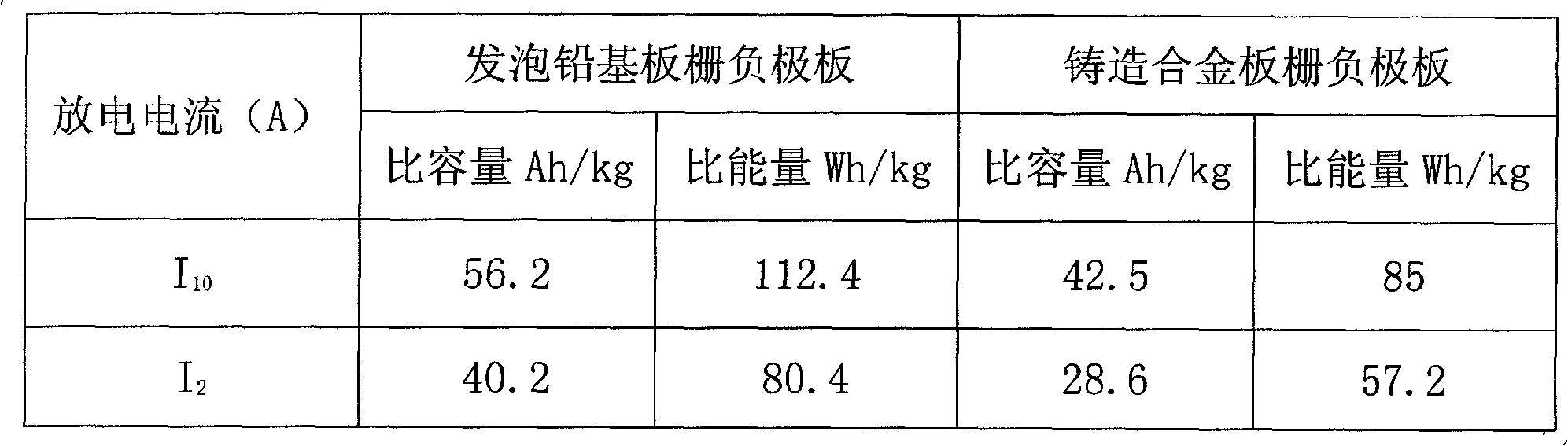
The invention discloses a lead-acid battery grid. The grid adopts a foamed lead-based board; the surface of the board and the profile in any direction of the board form irregular convex-concave faces (distributed with small honeycomb pores in the board). Compared with a casting alloy grid in the same size, the weight of the grid is reduced by 20 to 50 percent; the area of the foamed lead-based grid is 5 to 15 times of that of the casting alloy grid so as to increase the contact area of the foamed lead-based grid and active substances, reduce internal resistance and improve the utilization rate of the active substances; and the foamed lead-based grid has large negative board capacity, the capacity increases 10 to 30 percent and the specific energy increases 15 to 35 percent. The foamed lead-based grid has good mechanical performance and controllable alloy compositions, and can use pure lead, lead calcium alloy, tin-lead alloy, lead-calcium tin-aluminium alloy and rare earth alloy.
Description
Technical field: [0001] The invention relates to a lead-acid battery, in particular to a pole plate grid of the lead-acid battery. Background technique: [0002] The grid is an important part of the valve-regulated lead-acid battery, which is used to coat the active material and realize the charging and discharging function of the battery. The current grids are all made by casting, the cross-section of the ribs is triangular or trapezoidal, the junctions are at right angles, and the longitudinal and transverse ribs are evenly distributed. The contact area between the grid and the active material is small, and the utilization rate of the active material is low. Invention content: [0003] The technical problem to be solved by the present invention is to provide a lead-acid storage battery grid, which has a large contact area with the active material and a high utilization rate of the active material. [0004] The present invention is realized through the following technic...
Claims
Login to View More Application Information
Patent Timeline
 IPC IPC(8): H01M4/73
CPCY02E60/12Y02E60/10
Inventor 谢鸣生杨惠强任安福
Owner 张天任
Features
- R&D
- Intellectual Property
- Life Sciences
- Materials
- Tech Scout
- Unparalleled Data Quality
- Higher Quality Content
- 60% Fewer Hallucinations
Learn More Browse by: Latest US Patents, China's latest patents, Technical Efficacy Thesaurus, Application Domain, Technology Topic, Popular Technical Reports.
© 2025 PatSnap. All rights reserved.Legal|Privacy policy|Modern Slavery Act Transparency Statement|Sitemap|About US| Contact US: help@patsnap.com