Fan-cooled rotor in shaft of high-speed permanent magnet motor

A permanent magnet motor, high-speed technology, applied to the rotating parts of the magnetic circuit, the shape/style/structure of the magnetic circuit, etc., can solve the problems of irreversible high-temperature loss of magnetism, large eddy current loss, and rotor temperature rise of the permanent magnet of the rotor, so as to avoid Effects of loss of magnetization problem, reduction of temperature rise, and enhancement of stability and reliability

Inactive Publication Date: 2009-12-16
HARBIN UNIV OF SCI & TECH
View PDF0 Cites 15 Cited by
  • Summary
  • Abstract
  • Description
  • Claims
  • Application Information

AI Technical Summary

Problems solved by technology

[0004] The purpose of the present invention is to solve the problem of high-strength non-magnetic metal sheath or binding carbon fiber on the outer surface of the rotor permanent magnet of the existing high-speed permanent magnet motor, which leads

Method used


Image

  • Fan-cooled rotor in shaft of high-speed permanent magnet motor
  • Fan-cooled rotor in shaft of high-speed permanent magnet motor
  • Fan-cooled rotor in shaft of high-speed permanent magnet motor

Examples


specific Embodiment approach 1

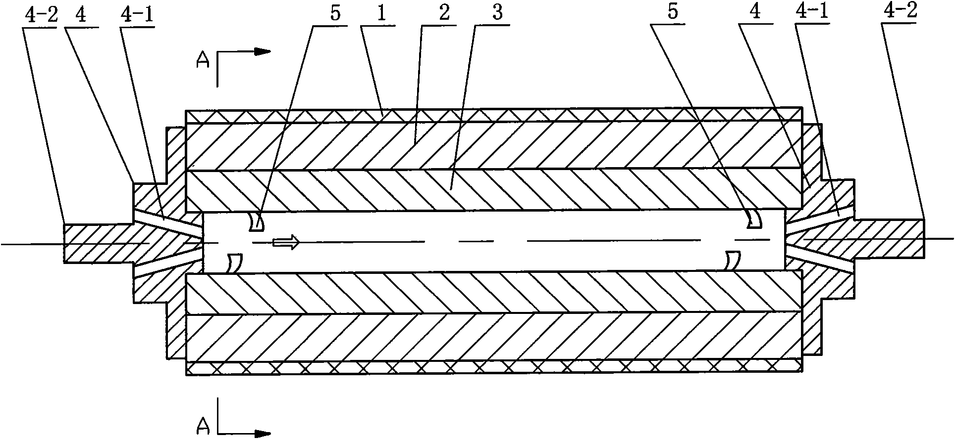
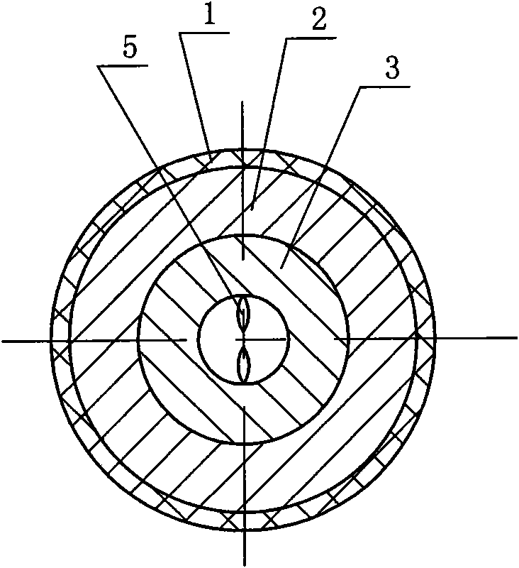
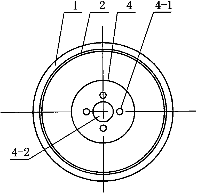
[0010] Specific implementation mode one: the following combination Figure 1 ~ Figure 3 Describe this embodiment, this embodiment comprises sheath or carbon fiber 1, permanent magnet 2 and rotor iron core 3, the permanent magnet 2 is encircled on the outer circular surface of rotor iron core 3, and the outer circular surface of permanent magnet 2 is provided with sheath or Carbon fiber 1, which also includes two end supports 4 and fan blades 5, the shoulders of the two end supports 4 are respectively interference fit with the two ends of the inner cavity of the rotor core 3, the end supports 4 and The rotor core 3 is coaxial, and the end support 4 is axially provided with a plurality of ventilation holes 4-1 communicating with the inner cavity of the rotor core 3 , and the inner cavity wall of the rotor core 3 is provided with fan blades 5 . When working, the output shaft 4-2 of the end support 4 is connected with the high-speed bearing of the motor to support the high-speed m...

specific Embodiment approach 2

[0011] Embodiment 2: The difference between this embodiment and Embodiment 1 is that the fan blade group 5 is a group of fan blade groups or two groups of fan blade groups, and the multiple fan blades of each group of fan blade group 5 are along the rotor core 3. The lumen wall is evenly distributed. Other components and connections are the same as those in Embodiment 1.

[0012] The multiple fan blades of each fan blade group 5 are evenly distributed along the inner cavity wall of the rotor core 3, which can enhance the stability of the motor when running at high speed.

specific Embodiment approach 3

[0013] Embodiment 3: The difference between this embodiment and Embodiment 2 is that the fan blade sets 5 form a set and are located at the air inlet end of the inner cavity wall of the rotor core 3 . Other components and connections are the same as those in Embodiment 2.

[0014] A group of fan blades are welded to the air inlet end of the inner cavity wall of the rotor core 3 to play the role of blowing air, and the self-fan cooling effect in the shaft is good.


PUM


Abstract

The invention provides a fan-cooled rotor in a shaft of a high-speed permanent magnet motor, which relates to a cooled rotor of the high-speed permanent magnet motor. The invention aims to solve the problems that when the outer surface of a rotor permanent magnet of the prior high-speed permanent magnet motor is provided with a high-strength non-magnetic metallic sheath or is bond with carbon fibers, the eddy current loss is large so that the temperature rise of the rotor is over-high and the rotor permanent magnet generates irreversible high-temperature magnetism loss. The fan-cooled rotor comprises a sheath or carbon fibers, a permanent magnet and a rotor core, wherein the surface of the outer circle of the rotor core is annularly sleeved with the permanent magnet and the surface of the outer circle of the permanent magnet is provided with the sheath or the carbon fibers. The fan-cooled rotor also comprises two end supporting parts and a fan blade group, wherein shoulders of the two end supporting parts are in interference fit with two ends of the inner cavity of the rotor core, the end supporting parts are coaxial with the rotor core and are provided with a plurality of air vents communicated with the inner cavity of the rotor core along the axial direction, and the wall of the inner cavity of the rotor core is provided with the fan blade group. The fan-cooled rotor is used as the rotor of the high-speed permanent magnet motor.

Description

technical field [0001] The invention relates to a cooling rotor of a high-speed permanent magnet motor, which belongs to the field of motors. Background technique [0002] High-speed permanent magnet motor not only has the characteristics of high speed, high power density, high material utilization rate, fast dynamic response and high efficiency of transmission system of ordinary high-speed motors, but also has the advantages of high efficiency and high power factor, so it is used in air conditioners or Centrifugal compressors for refrigerators, energy storage flywheels, textiles, high-speed grinders, hybrid vehicles, aviation, ships and other fields have good application prospects. Especially in the distributed power generation system, due to the small size and high mobility of the high-speed permanent magnet generator driven by the gas turbine, it can be used as a backup power source for hospitals, hotels and other important facilities, and can also be used as an independe...

Claims


Application Information

Patent Timeline
IPC IPC(8): H02K1/32
Inventor 李伟力张晓晨耿加民霍菲阳曹君慈沈稼丰
Owner HARBIN UNIV OF SCI & TECH
Why Eureka
Try Eureka