
Check fire valve for flue

A fire damper and non-return technology, applied in the direction of control valve, safety valve, balance valve, etc., can solve the problems of not having the forced closing position of the valve plate, the effect of exhausting oil fume is worse, and threatening the life safety of residents.

Active Publication Date: 2009-12-23
韩文强
View PDF0 Cites 25 Cited by
  • Summary
  • Abstract
  • Description
  • Claims
  • Application Information

AI Technical Summary

Problems solved by technology

When the range hood is not in use, the valve is in the closed position due to its own gravity, covering the air outlet; when the range hood is in use, the valve is in the open position, and the valve is far away from the air outlet, because the plane where the valve is located when the valve is opened Consistent with the cross-section of the longitudinal public flue, the open valve will hinder the smooth flow of the public flue, especially in the case of a multi-storey residential building sharing a longitudinal public flue, the opened valve of each floor will seriously hinder the flow of the public flue. The smoothness of the public flue gas duct makes the effect of exhausting oil fume worse
At the same time, since many users share a vertical public flue gas passage, once a fire breaks out in one household, a large amount of high-temperature harmful gas will flow into the vertical public flue gas passage. If the valve plate in the flue check valve is not closed in time, These large amounts of high-temperature and harmful gases will enter the homes of users who are using range hoods through the fume passage of the flue check valve, thereby threatening the lives of residents. s method

Method used


Image

  • Check fire valve for flue
  • Check fire valve for flue
  • Check fire valve for flue

Examples


Embodiment Construction

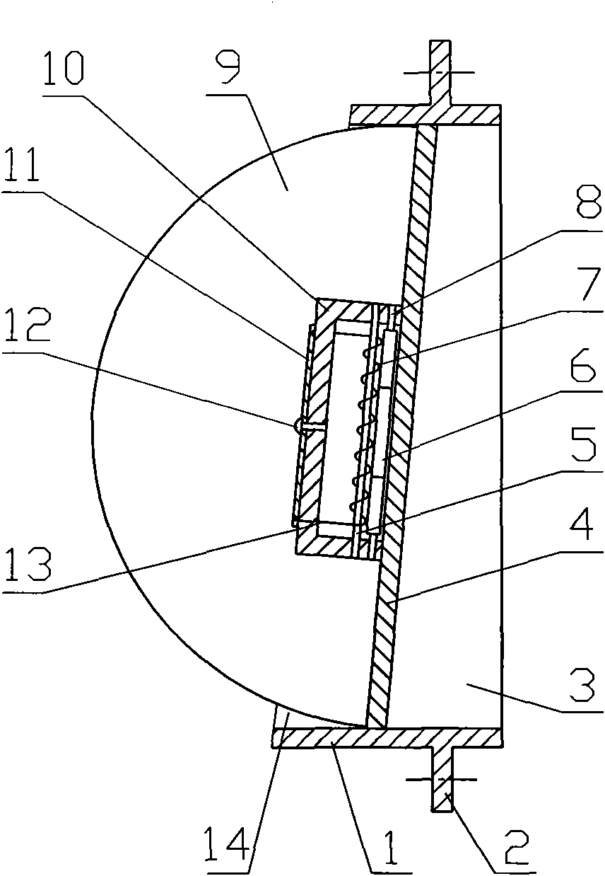
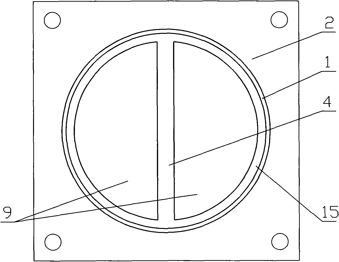
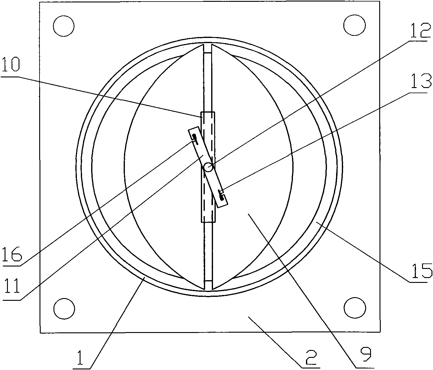
[0020] Figure 1-Figure 3 The shown flue check fire damper includes a cylindrical oil fume passage formed by the casing 1. The oil fume passage can be a variable-diameter passage. The oil fume passage has an opposite air inlet 3 and an air outlet 14 (that is, the opposite The air inlet channel and the air outlet channel), the outer wall of the housing 1 is provided with a mounting plate 2, and the end of the oil fume channel near the air inlet 3 is provided with a blocking body 15. The blocking body 15 is an annular body arranged on the inner wall of the oil fume channel. The blocking body 15 can also be a boss arranged on the inner wall of the oil fume passage or convex points arranged at annular intervals along the inner wall of the oil fume passage. In the fume passage, near the side of the air inlet 3, there is a vertically arranged connecting strip 4 that divides the air inlet 3 into two parts. The connecting strip 4 and the blocking body 15 can be integrally arranged, su...


PUM


Abstract

The invention discloses a check fire valve for a flue, comprising a lampblack channel comprising an outer casing. The lampblack channel is provided with an air inlet and an air outlet which are opposite to each other; two oppositely arranged valve plates are arranged in the lampblack channel; and are rotatablely arranged in the lampblack channel through a valve plate rotation shaft; a blocking body causing the two valve plates only to be opened towards the direction of the air outlet is arranged at one end near the air inlet in the lampblack channel; a connecting strip lengthways arranged to separate the air inlet to two parts is arranged at the side near the air inlet in the lampblack channel; the valve plate rotation shaft is arranged close to the connecting strip; and the side face of the connecting strip facing to the air outlet is provided with a high-temperature closing device which can enable the valve plates to be forcibly closed. The invention has good lampblack removing effect, can not impede the smoothness of public flues, and can be forcibly closed when temperature of flue gas in the public flues is in a high exigent condition.

Description

technical field [0001] The invention relates to a flue non-return fire damper used in kitchens using public flue flues. Background technique [0002] In kitchens using longitudinal public flue ducts, in order to prevent oily fumes from flowing back into the kitchen, a check valve such as a flue check valve is generally installed between the outlet pipe of the range hood and the public flue duct. device. Existing flue check valves generally include an oil fume passage formed by a casing. The oil fume passage has opposite air inlets and air outlets. The air inlet is connected to the outlet pipe of the range hood. In the air duct, an openable and closable valve plate is arranged at the air outlet of the oil fume channel, and the valve plate is rotated and installed on the inner wall of the oil fume channel through the horizontally arranged valve plate rotating shaft, and the valve plate rotating shaft is located above the center of the valve plate. When the range hood is not ...

Claims


Application Information

Patent Timeline
IPC IPC(8): F16K15/03F16K17/38F16K17/40
CPCC04B2103/0005C04B2111/00017C04B2103/61C04B40/0039Y02W30/91C04B12/04C04B18/146C04B22/0013C04B22/062C04B22/10C04B24/04C04B24/045C04B24/06C04B24/122C04B28/02
Inventor 韩文强
Owner 韩文强
Learn More