Hydraulic control system of steel tube clamping device in hydraulic pressure test tube machine

A clamping device and clamping hydraulic cylinder technology, applied in fluid pressure actuating devices, measuring devices, mechanical equipment, etc., can solve problems such as rupture of connecting oil pipes, accidents, heightening, etc., to ensure accuracy and improve production rhythm Effect

A clamping device and clamping hydraulic cylinder technology, applied in fluid pressure actuating devices, measuring devices, mechanical equipment, etc., can solve problems such as rupture of connecting oil pipes, accidents, heightening, etc., to ensure accuracy and improve production rhythm Effect

CN101608987BInactive Publication Date: 2011-05-18TAIYUAN HEAVY IND +1

Image

  • Hydraulic control system of steel tube clamping device in hydraulic pressure test tube machine
  • Hydraulic control system of steel tube clamping device in hydraulic pressure test tube machine
  • Hydraulic control system of steel tube clamping device in hydraulic pressure test tube machine

Examples


Embodiment Construction

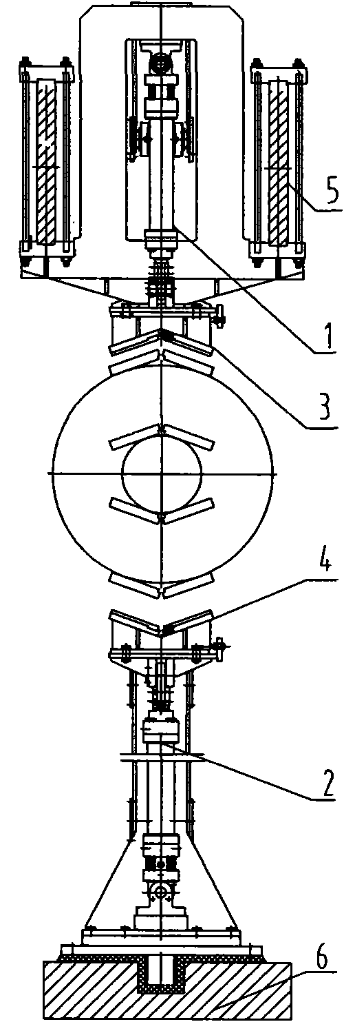
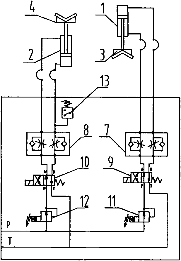
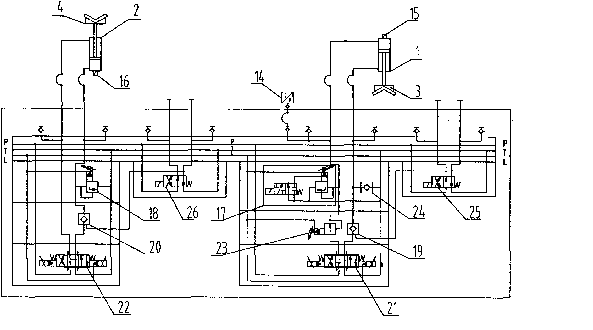
[0021] Such as image 3 As shown, a hydraulic control system of a steel pipe clamping device in a hydraulic test tube machine is mainly composed of an upper clamping hydraulic cylinder 1 and an upper clamp 3 installed on the head of its piston rod, a lower clamping hydraulic cylinder 2 and its piston The lower fixture 4 installed on the head of the rod is composed of a hydraulic control circuit formed by a conventional connection method including an electromagnetic reversing valve, a pressure reducing valve and a hydraulic oil pipe. The upper clamping hydraulic cylinder 1 is equipped with a displacement sensor 15, and is connected with a pressure sensor 14, an electromagnetic overflow valve 17, a one-way valve 24, a pressure reducing valve 23, and No. I hydraulic control one-way valve 19 and I according to a conventional connection method. No. proportional reversing valve 21, No. III electromagnetic reversing valve 25 and hydraulic oil pipe form a hydraulic control circuit; th...


PUM


Abstract

A hydraulic control system of a steel tube clamping device in a hydraulic pressure test tube machine relates to the hydraulic control systems of rolling machinery. The system comprises an upper clamping hydraulic cylinder internally provided with a displacement sensor, an upper clamp arranged at the head of a piston rod, a lower clamping hydraulic cylinder internally provided with a displacement sensor and a lower clamp arranged at the head of the piston rod; a pressure sensor, an electromagnetic relief valve, a one-way valve, a reducing valve, a No.I hydraulic control one-way valve, a No.I proportional reversing valve, an electromagnetic reversing valve and a hydraulic oil tube form a hydraulic control circuit of the upper clamping hydraulic cylinder; a relief valve, a No.II hydraulic control one-way valve, a No.II proportional reversing valve, an electromagnetic reversing valve and a hydraulic oil tube form a hydraulic control circuit of the lower clamping hydraulic cylinder. The system effectively controls the stroke and the maximum clamping force of the hydraulic cylinder, accelerates the production rhythm, ensures the accuracy of the clamping device location and plays a role of safety protection of the pressure test steel tubes in the process of pressure test.

Description

technical field [0001] The invention belongs to a hydraulic control system of a steel rolling machine, and in particular relates to the hydraulic control of a clamping device in a large-diameter straight seam submerged arc welded steel pipe hydraulic test tube machine. Background technique [0002] During the pressure test of the hydraulic test tube machine, the lifting device lifts the steel pipe to be tested to the position of the center line of the pressure test, and the steel pipe is pressed tightly by the front and rear pressure heads with seals. At this time, the clamping device located in the middle of the steel pipe needs to clamp the steel pipe, that is, the piston rod of the upper clamping hydraulic cylinder protrudes downwards, and the piston rod of the lower clamping hydraulic cylinder protrudes upwards. Type clamps clamp the steel pipe. After the steel pipe is clamped, the lifting device descends and resets. The steel pipe starts to be filled with low-pressure...

Claims


Application Information

Patent Timeline
18 May 2011
Publication
CN101608987B
IPC
G01N3/04; F15B11/16
Inventors
张英婵; 贾卫东