Acceleration and deceleration control device and acceleration and deceleration control method

An acceleration and deceleration control, acceleration and deceleration technology, applied in the direction of digital control, program control, electrical program control, etc., can solve problems such as corner error, achieve the effect of smooth jerk curve, processing precision and product quality

Inactive Publication Date: 2009-12-23
HONG FU JIN PRECISION IND (SHENZHEN) CO LTD +1
View PDF0 Cites 10 Cited by
  • Summary
  • Abstract
  • Description
  • Claims
  • Application Information

AI Technical Summary

Problems solved by technology

In addition, this method will also produce a corner error; and the peak E of the jerk (Jerk) curve is also relatively sharp ( Figure 4 shown)

Method used


Image

  • Acceleration and deceleration control device and acceleration and deceleration control method
  • Acceleration and deceleration control device and acceleration and deceleration control method
  • Acceleration and deceleration control device and acceleration and deceleration control method

Examples


Embodiment Construction

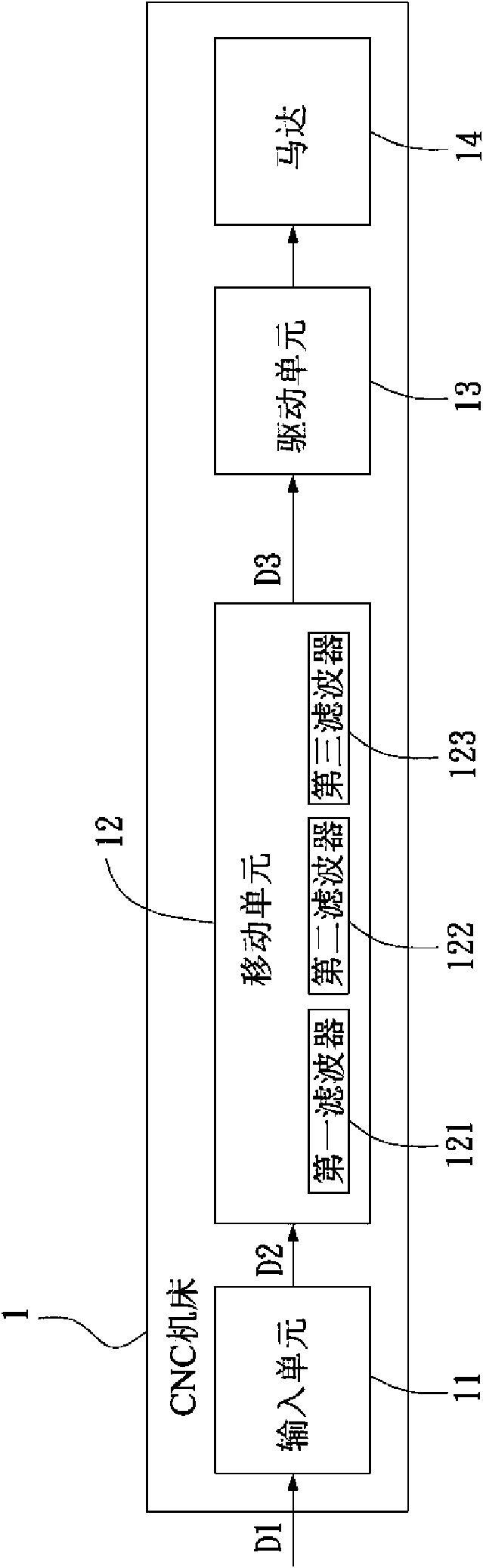
[0026] Please refer to Figure 5 As shown, the preferred embodiment of the acceleration and deceleration control device of the present invention is used for acceleration and deceleration planning of a CNC machine tool, which includes an interpolation arithmetic unit 21, a movement unit 22, a drive conversion unit 23, and an A motor 24 that drives a tool or a work platform 25.

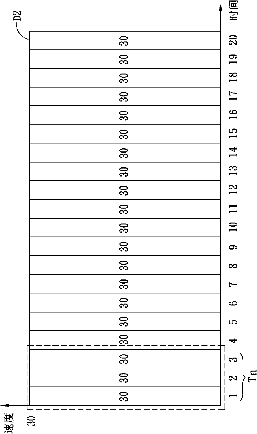
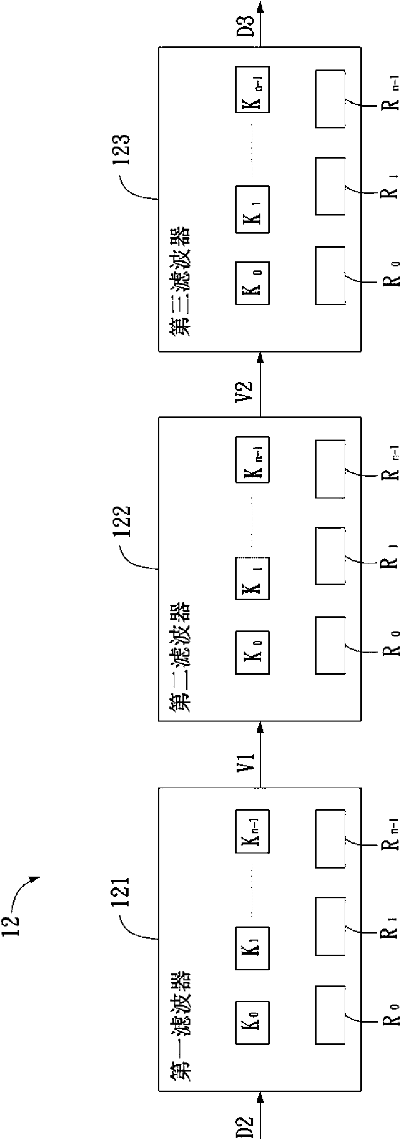
[0027] The interpolation arithmetic unit 21 is used to receive a speed command S1, and obtain a pulse speed Vx (such as Figure 7 Shown); The mobile unit 22 includes an arithmetic filter 221 to receive the pulse velocity Vx; Figure 6 As shown, the arithmetic filter 221 includes a plurality of buffers 2212, and these buffers 2212 respectively have a different weight value ω 0 , Ω 1 ...ω n-1 . The arithmetic filter 221 uses a first function to determine the pulse velocity Vx and each weight value ω 0 , Ω 1 ...ω n-1 , Calculate an acceleration and deceleration pulse V′x (such as Figure 8 Shown), these weight...


PUM


Abstract

The invention provides an acceleration and deceleration device which is used for controlling the acceleration and deceleration of a CNC lathe. The device comprises an interpolation arithmetic unit, a movable unit and a drive conversion unit. The interpolation arithmetic unit is used for processing a speed command by interpolation arithmetic and outputting a pulse speed. The movable unit comprises an arithmetic filter which comprises a plurality of buffers, and each buffer stores a weight value; the movable unit works out an acceleration and deceleration pulse by utilizing a first functional according to the pulse speed and the weight values of the buffers. The drive conversion unit is used for converting the acceleration and deceleration pulse into a drive signal so as to drive a motor. The invention can improve the processing precision and the product quality. The invention also provides an acceleration and deceleration method.

Description

Technical field [0001] The invention relates to an acceleration / deceleration control device and an acceleration / deceleration control method of a CNC (Computer Numerical Control) machine tool. Background technique [0002] The CNC machine tool uses the CNC system to combine the mechanical actions of the machine tool, and by inputting processing instructions, the machine tool controls the movement of the processed parts. However, due to the higher and higher functional requirements for machine tools, in addition to requiring the size of the computer and the driving equipment to be reduced, it is also hoped that the machining accuracy can be higher and higher. [0003] Therefore, when the rate of change of processing speed is too large, it is necessary to use a control system to make an acceleration and deceleration plan, so that the CNC machine tool has a smoother processing speed curve to improve the processing accuracy. Therefore, the acceleration and deceleration planning contro...

Claims


Application Information

Patent Timeline
Patent Type & Authority Applications(China)
IPC IPC(8): G05B19/416
CPCG05B2219/43049G05B19/4163G05B2219/43036
Inventor 金岳勳邱志豪
Owner HONG FU JIN PRECISION IND (SHENZHEN) CO LTD
Why Eureka
Try Eureka