Oil mist separation device used for mechanical and electrical equipment and separation method

A technology for oil mist separation and electromechanical equipment, applied in separation methods, combined devices, dispersed particle separation, etc., can solve problems such as damage to the physical and mental health of workers, waste of resources, and no oil mist separation system purification device, and achieve filtration efficiency. Efficient and durable, improving machining precision, and the effect of insignificant changes in efficiency

Inactive Publication Date: 2018-07-03
哈尔滨获强商贸有限公司
View PDF0 Cites 1 Cited by
  • Summary
  • Abstract
  • Description
  • Claims
  • Application Information

AI Technical Summary

Problems solved by technology

[0002] During the processing of CNC machine tools, a large amount of oil mist containing polychlorinated biphenyls is generally produced, which implicitly damages the physical and mental health of the staff. The currently used Most of the electromechanical equipment is not equipped with an oil mist separation system purification device. The oil mist in the electromechanical equipment is inhaled into the human body at a particle size of 0.3-3.5 microns, which will pose a health hazard. The oil mist is deposited in the work area, which is likely to cause work-related accidents
[0003]A large amount of oil mist generated by electromechanical equipment during high-speed cutting is adsorbed on equipment and workpieces for a long time, which may cause failures in the machine tool and electrical systems, and bring troubles to the maintenance of machine tools It is not a small trouble, but also greatly reduces the processing precision of the machine tool, and at the same time wastes resources and damages the environment. If the oil mist gas is discharged to the outside, it will damage the environment. If it can be recycled effectively, it can save resources and the oil mist will be deposited for a long time Potential fire hazards on walls and equipment

Method used


Image

  • Oil mist separation device used for mechanical and electrical equipment and separation method

Examples


Embodiment 1

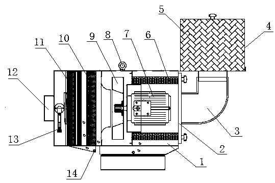
[0024] An oil mist separation device for electromechanical equipment, which consists of: a base 1, the base has a groove, the middle part of the groove is installed with a motor 7, and the sides of the motor are respectively installed with two three Stage filtering device 6, the front end of the motor is connected to the centrifugal impeller 9 through a connecting shaft, the front end of the centrifugal impeller is equipped with a secondary filtering device 10, the front end of the secondary filtering device is equipped with a primary filtering device 11, the An oil mist suction port 12 is installed on the front end of the base.

Embodiment 2

[0026] According to the oil mist separation device for electromechanical equipment described in Embodiment 1, the front end surface of the three-stage filter device is attached to the side surface of the inner groove of the base, and the rear end surface of the three-stage filter device is in contact with the inner surface of the end cover 2. The end faces are bonded, and the end cover is connected with the bottom plate through bolts.

Embodiment 3

[0028] According to the oil mist separation device for electromechanical equipment described in Embodiment 2, the end cover has a hole, and a connecting elbow 3 is installed in the hole, and the connecting elbow is connected to the high-efficiency filter 5 through the connecting joint. Connection, the side of the high-efficiency filter has a clean air outlet 4.


PUM


Abstract

The invention relates to an oil mist separation device used for mechanical and electrical equipment and a separation method. Most of currently used mechanical and electrical devices do not have an oilmist separation system purifying device, oil mist in the mechanical and electrical equipment is inhaled into the human body at the particles of 0.3-3.5 micrometers and causes harm to the health, anddeposition of the oil mist in the working area easily causes occupational injury and other accidents. The oil mist separation device comprises a base (1), wherein a groove is formed in the base (1), an electric motor (7) is arranged in the middle position in the groove, two tertiary filtering devices (6) are respectively arranged on the side faces of the electric motor, the front end of the electric motor is connected with a centrifugal impeller (9) by a connecting shaft, a secondary filtering device (10) is arranged at the front end of the centrifugal impeller, a primary filtering device (11)is arranged at the front end of the secondary filtering device, and an oil mist suction port (12) is arranged at the front end face of the base. The invention discloses the oil mist separation deviceused for mechanical and electrical equipment and the separation method.

Description

Technical field: [0001] The invention relates to electromechanical equipment, in particular to an oil mist separation device and method for electromechanical equipment. Background technique: [0002] During the processing of CNC machine tools, a large amount of oil mist containing polychlorinated biphenyls is generally produced, which implicitly damages the physical and mental health of the staff. Most of the electromechanical equipment currently in use does not have an oil mist separation system purification device. The inhalation of the oil mist in the 0.3-3.5 micron particles in the human body will pose a health hazard, and the oil mist will be deposited in the work area, which may easily cause accidents such as work-related injuries. [0003] A large amount of oil mist generated by electromechanical equipment during high-speed cutting is adsorbed on the equipment and workpiece for a long time, which may cause failures in the machine tool and the electrical system, which ...

Claims


Application Information

Patent Timeline
Patent Type & Authority Applications(China)
IPC IPC(8): B01D50/00B23Q11/00
CPCB01D50/00B23Q11/00B23Q11/0078
Inventor 姜帅
Owner 哈尔滨获强商贸有限公司
Why Eureka
Try Eureka