
Generator drive device, hybrid vehicle, and generator drive device control method

A driving device and generator technology, applied in hybrid vehicles, synchronous generator control, engine-driven traction, etc., to achieve stable voltage control and avoid inrush current effects

Inactive Publication Date: 2013-01-16
KOMATSU LTD
View PDF2 Cites 0 Cited by
  • Summary
  • Abstract
  • Description
  • Claims
  • Application Information

AI Technical Summary

Problems solved by technology

However, when a booster mechanism is provided in a conventional motor drive device, there is a problem that a large current (inrush current) must be avoided when the contactor is turned on when the engine is started.

Method used


Image

  • Generator drive device, hybrid vehicle, and generator drive device control method
  • Generator drive device, hybrid vehicle, and generator drive device control method
  • Generator drive device, hybrid vehicle, and generator drive device control method

Examples


Embodiment Construction

[0023] Hereinafter, the best mode for carrying out the present invention (hereinafter referred to as "embodiment") will be described with reference to the drawings.

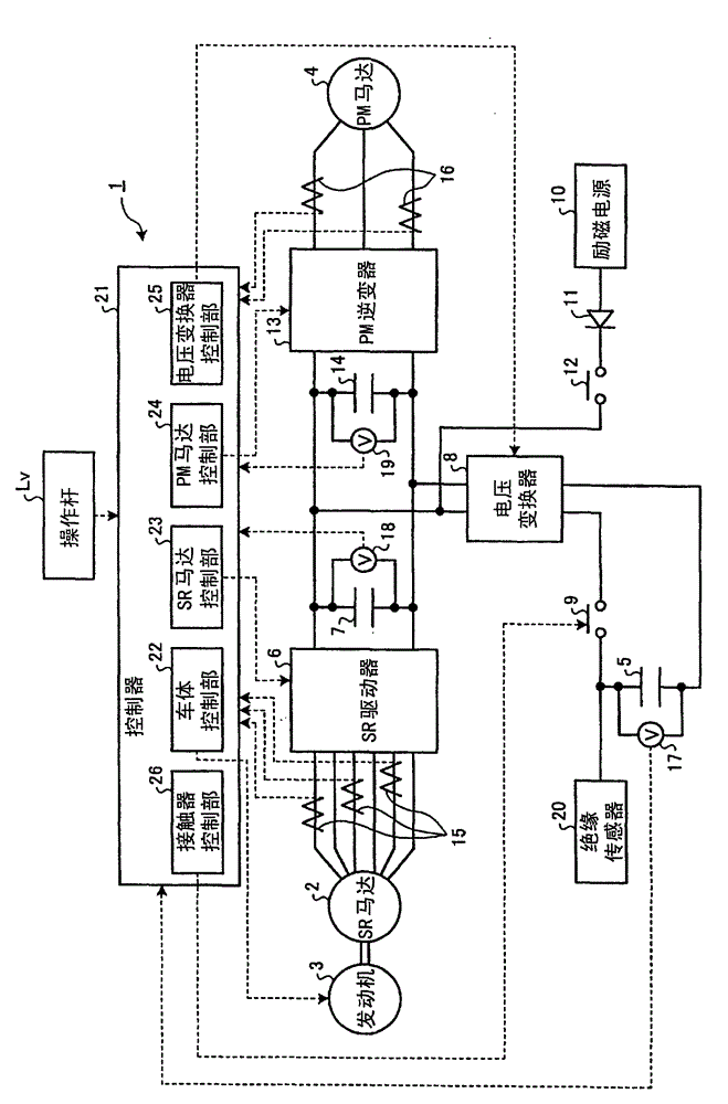
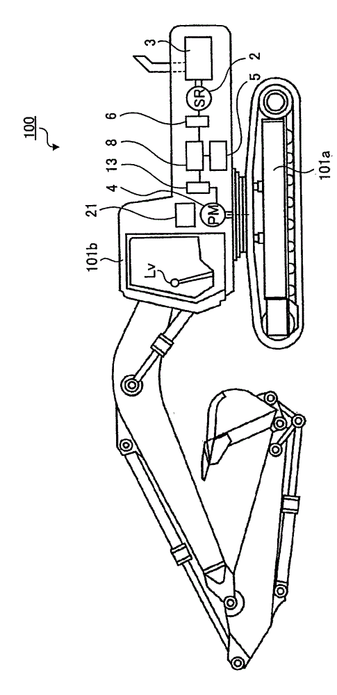
[0024] figure 1 It is a figure which shows the structure of the generator driving apparatus which concerns on one Embodiment of this invention. The generator drive device 1 shown in the figure is mounted on a hybrid vehicle. In Embodiment 1, the hybrid vehicle equipped with the generator drive device 1 is figure 2 A hydraulic excavator 100 is shown. The hydraulic excavator 100 includes: a self-propelled portion 101a that is self-propelled by the rotation of the crawler belt; a working device such as a bucket, a boom, and an arm, and a cab; Section 101b. The generator drive unit 1 mounted on the hydraulic excavator 100 having such a structure includes a generator whose drive shaft is connected to a drive shaft of an engine, and a swing motor having a drive shaft that coincides with the swing axis of the swing...


PUM


Abstract

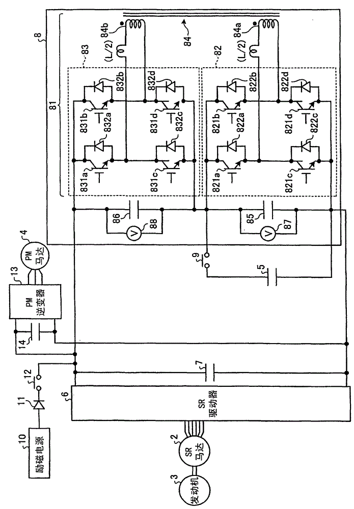
In order to securely prevent, even where a boosting unit is provided, a rush current from arising when a contactor is turned on during a transient state, the voltage of a surge absorbing condenser is controlled so that the voltage difference between the power source capacitor and surge absorbing condenser falls in a predetermined range. The control is performed in the following manner: of the two voltage source inverters of the AC-coupled bi-directional DC-DC converter composing a voltage converter as a boosting unit, only the one that is not connected in parallel with a power source capacitor is activated to perform a chopping operation while the generator is operated with the contactor off.

Description

technical field [0001] The present invention relates to a generator drive device that drives an electric motor as a generator, a hybrid vehicle equipped with the generator drive device, and a control method for the generator drive device. Background technique [0002] Conventionally, a motor drive device for a hybrid vehicle equipped with an engine and a motor as a drive source includes an inverter for driving the motor, and a large-capacity capacitor that supplies power to the motor through the inverter and stores the electric power generated by the motor. A storage battery such as a cayapashita, a capacitor connected in parallel with the storage battery, a mechanism for adjusting the generated voltage of a motor, and a contactor connected in series between the storage battery and the capacitor (for example, refer to Patent Document 1). According to the motor drive device having such a structure, the motor can be used as a generator while adjusting the generated voltage of ...

Claims


Application Information

Patent Timeline
Patent Type & Authority Patents(China)
IPC IPC(8): H02P9/08B60L11/14B60L3/00B60L50/15B60L50/16H02P25/08H02P101/25H02P101/45H02P103/20
CPCY02T10/6217H02M1/36B60L2220/18H02P9/08Y02T10/7022Y02T10/725B60L2210/10Y02T10/7216B60L11/123Y02T10/7077B60L2210/20Y02T10/642B60L50/61Y02T10/62Y02T10/64Y02T10/70Y02T10/72B60K6/26B60W10/08Y02T10/7072
Inventor 佐藤知久
Owner KOMATSU LTD
Learn More