Sleeve spool valve structure featuring rigid cutting-off

A technology for sleeve valves and spools, applied in sliding valves, valve devices, engine components, etc., can solve the problem that the working temperature cannot be strictly cut off, and achieve the effect of reducing fluid noise

Inactive Publication Date: 2009-12-30
SHANGHAI INST OF PROCESS AUTOMATION & INSTR +1
View PDF0 Cites 6 Cited by
  • Summary
  • Abstract
  • Description
  • Claims
  • Application Information

AI Technical Summary

Problems solved by technology

[0004] The present invention aims to solve the problem that the existing sleeve valve core structure cannot achieve tight shutoff when the working temperature changes, and provides a sleeve valve core structure that can achieve tight shutoff during production and actual use.

Method used


Image

  • Sleeve spool valve structure featuring rigid cutting-off
  • Sleeve spool valve structure featuring rigid cutting-off

Examples


Embodiment Construction

[0012] Below in conjunction with accompanying drawing, the present invention is described in further detail:

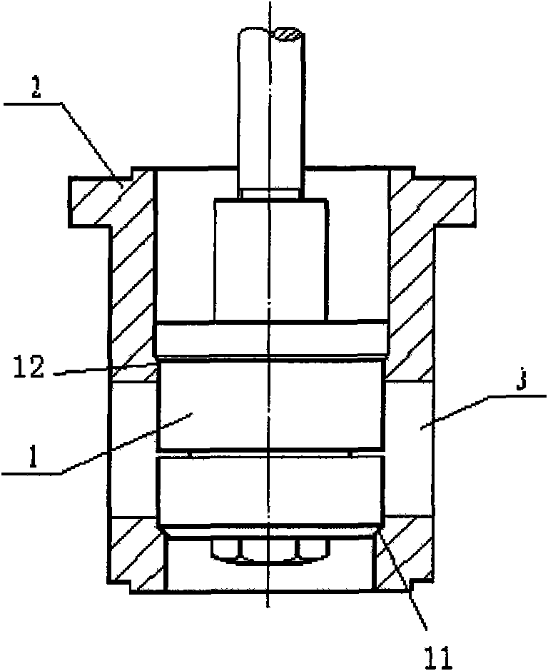
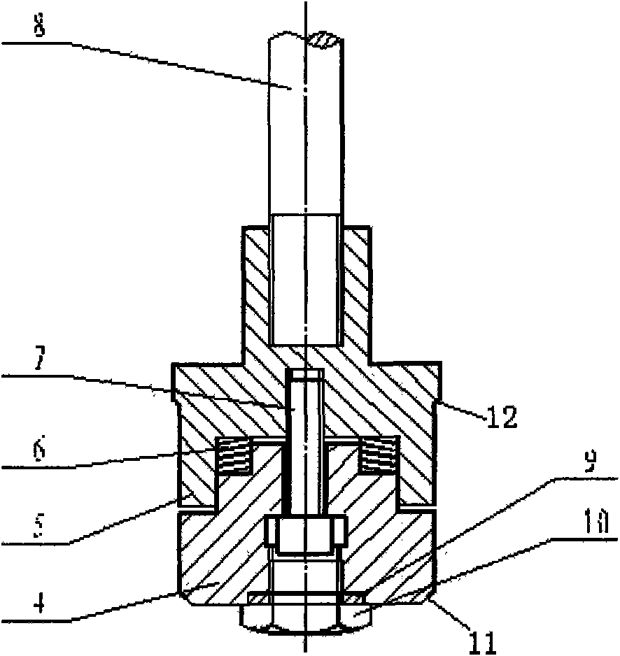
[0013] Such as figure 1 , Shown in 2, the sleeve valve structure of the tight shutoff of the present invention, it is made up of spool assembly 1, sleeve 2. The spool assembly 1 includes a lower spool 4 , an upper spool 5 , a disc spring set 6 , a screw 7 , a valve stem 8 , a sealing gasket 9 and a sealing bolt 10 .

[0014] The 60° to 90° sealing tapered surface of the lower valve core 4 and the 60° to 90° conical valve seat at the bottom of the sleeve 2 form a lower seat seal. The 60° to 90° sealing cone surface 12 of the upper valve core 5 and the 60° to 90° conical valve seat on the top of the sleeve 2 form an upper valve seat seal. The disc spring group 6 is clamped between the lower spool 4 and the upper spool 5, and its elastic deformation can eliminate the gap between the upper and lower valve seat seals due to factors such as temperature changes, so that th...


PUM


Abstract

The invention relates to a sleeve spool valve structure featuring rigid cutting-off, comprising a spool valve component and a sleeve. The edge of an upper spool valve boss is provided with a sealing cone of 60 degrees to 90 degrees which has the function of self-centering, and the sealing cone and a conical valve seat of 60 degrees to 90 degrees on the upper part of the sleeve form upper valve seat sealing; a lower end mouth of a lower spool valve is provided with a sealing cone of 60 degrees to 90 degrees which has the function of self-centering, and the sealing cone and the conical valve seat of 60 degrees to 90 degrees at the lower part of the sleeve form lower valve seat sealing; a group of disk-shaped springs are clamped between the upper spool valve and the lower spool valve, and bolts are used for connecting and pretightening the disk-shaped springs. The sealing surfaces of upper and lower valve seats as well as upper and lower spool valves of the sleeve are designed into conical surfaces of 60 degrees to 90 degrees, the conical surfaces can perform self-centering when contacting with each other; the spool valve is designed as a segregated structure, a group of disk-shaped springs are clamped between the upper spool valve and the lower upper spool valve, the flexible deformation thereof can remove clearance generated at the sealing part of the upper and lower valve seats due to temperature changes, so that the sealing surface can remain completely fit to meet the requirements of rigid cutting-off.

Description

technical field [0001] The invention relates to a sleeve valve core structure, in particular to a double valve seat sleeve valve core structure. Background technique [0002] The double-seat sealed sleeve regulating valve uses the principle of pressure balance to minimize the resultant force of the medium acting on the valve core, and its driving force can be reduced by 70% to 80% compared with the driving force of the single-seat regulating valve of the same specification. The sleeve valve core structure It also has the effect of reducing fluid noise by 20dB to 30dB. [0003] Due to the limitation of processing precision of the existing double-seat sleeve valve core structure, the upper and lower valve seats of the sleeve and the upper and lower sealing surfaces of the valve core cannot be in contact at the same time, and there is always a gap in one place, which cannot be reached. Strict cut-off requirements. Even if the tight cut-off is achieved through complex processe...

Claims


Application Information

Patent Timeline
Patent Type & Authority Applications(China)
IPC IPC(8): F16K3/04F16K3/314F16K3/32
Inventor 陈蒙南吴刚陈英
Owner SHANGHAI INST OF PROCESS AUTOMATION & INSTR
Why Eureka
Try Eureka