Optical fiber integration antenna and signal transmission method

An optical fiber and antenna technology, which is applied in the field of optical fiber integrated antenna and signal transmission, can solve the problems of large volume and installation complexity, increased cost, thick diameter, etc., and achieve the effects of improving communication quality, considerable savings, and convenient installation

Inactive Publication Date: 2009-12-30
俞元明 +2
View PDF0 Cites 9 Cited by
  • Summary
  • Abstract
  • Description
  • Claims
  • Application Information

AI Technical Summary

Problems solved by technology

The disadvantage of coaxial cable is that the diameter is relatively thick, the attenuation is relatively large, and the cost of long-distance transmission is high
Frequently used multi-sector antenna components require multiple amplifiers to be connected to the remote processing unit through multiple coaxial cables, and the size and installation complexity are relatively large
First of all, the problem of attenuation increases the power loss of the transmission, wasting a lot of energy, and the

Method used


Image

  • Optical fiber integration antenna and signal transmission method
  • Optical fiber integration antenna and signal transmission method
  • Optical fiber integration antenna and signal transmission method

Examples


Embodiment 1

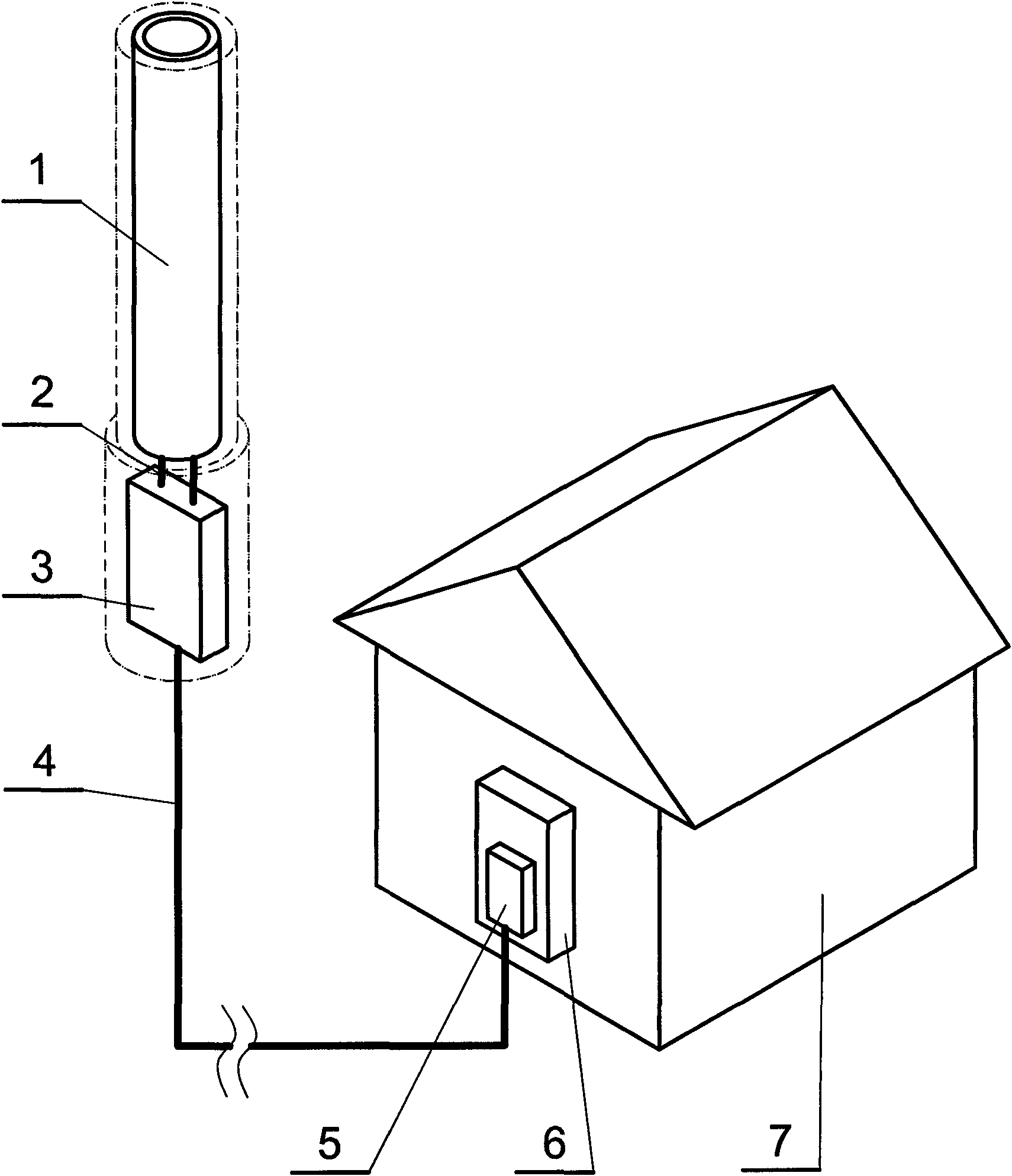
[0017] This embodiment is an optical fiber integrated antenna, such as figure 1 shown. This embodiment includes an antenna assembly 1 installed outdoors, the antenna assembly is connected to the remote processing unit 3 through a macro-distance radio frequency connection assembly 2, and the remote processing unit is connected to a long-distance optical cable 4 , the long-distance optical cable is connected to the near-end optical fiber remote processing unit 5 in the wireless communication base station equipment room 7, and the remote optical fiber near-end processing unit is connected to the signal source device 6.

[0018] In this embodiment, the common passive antenna assembly and the optical fiber remote processing unit are combined, or they are installed in one casing, or the antenna assembly and the optical fiber remote processing unit are respectively installed in two separate housings for the purpose of shielding. In the housing, two independent housings are rigidly c...

Embodiment 2

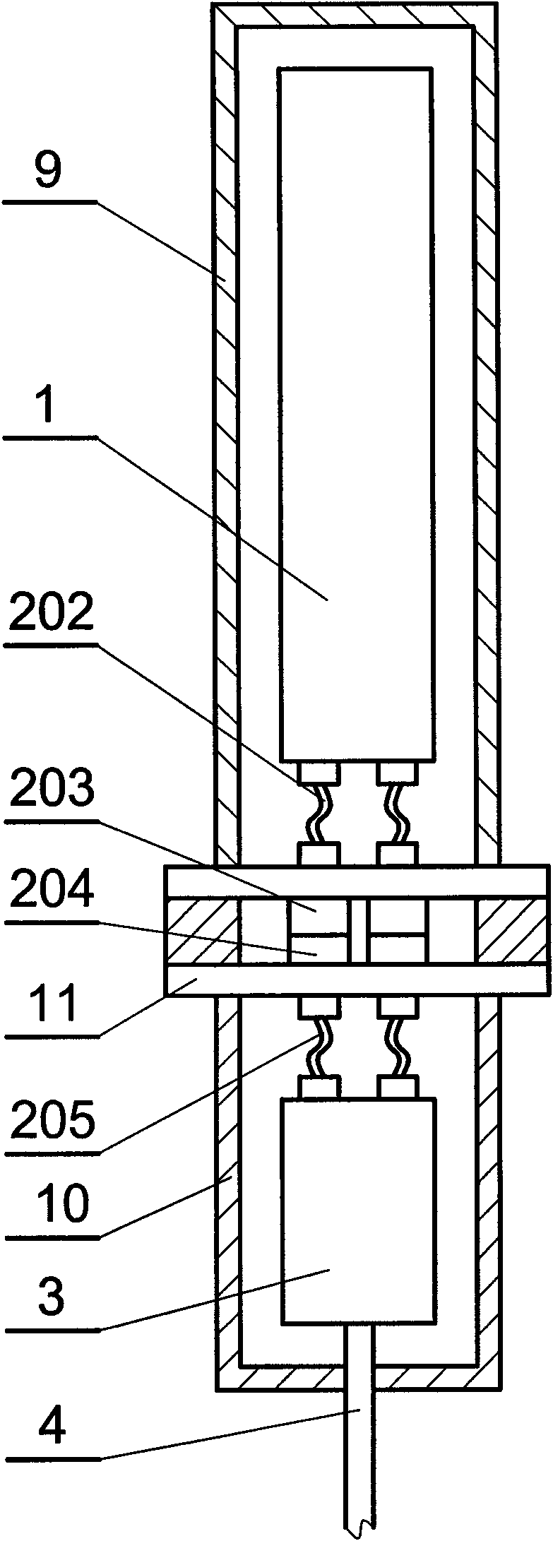
[0023] This embodiment is an improvement of the first embodiment, and is a refinement of the first embodiment about the macro-distance radio frequency connection component. The macro-distance radio frequency connection assembly described in this embodiment is one or a combination of radio frequency connection jumpers or radio frequency coaxial connectors.

[0024] One of the macro-distance radio frequency connection components described in this embodiment is a radio frequency connection jumper, which is a semi-steel and semi-flexible cable, such as SFT-50-3-1, SFF and other types of cables. Another macro-distance RF connection component is a RF coaxial connector, such as L29-J-K and other models. More often, the combination of two connection devices is used. Because the RF connection jumper is suitable for connecting two very close RF modules in a shielded shell, and the RF coaxial connector is suitable for connecting two RF modules through a rigid shell, and before passing t...

Embodiment 3

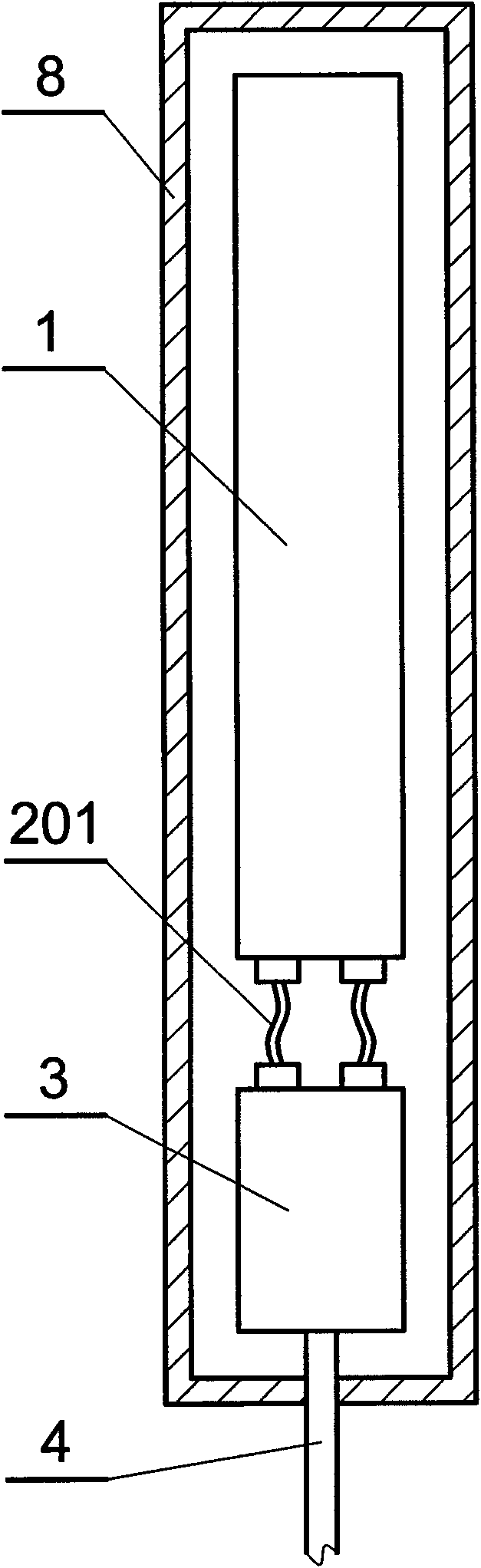
[0026] This embodiment is an improvement of the second embodiment, and is a refinement of the second embodiment regarding the macro-distance radio frequency connection component. The antenna assembly and the optical fiber remote processing unit described in this embodiment are installed in the same housing 8, and the macro-distance radio frequency connection assembly connected between the antenna assembly and the optical fiber remote processing unit is a radio frequency connection jumper line 201, as in figure 2 shown.

[0027] In the optical fiber integrated antenna described in this embodiment, the antenna assembly and the optical fiber remote processing unit are arranged in a casing, and the connection between the two uses a radio frequency connection jumper, and the connection distance is very short.


PUM

PropertyMeasurementUnit
Lengthaaaaaaaaaa
Lengthaaaaaaaaaa

Abstract

The invention relates to an optical fiber integration antenna and a signal transmission method which are an antenna device and a signal transmission method used in a wireless communication base station in a wireless communication network. The optical fiber integration antenna comprises an antenna assembly arranged outdoors, the antenna assembly is connected with an optical fiber remote far-end processing unit via a micro-distance radio frequency connecting assembly, the optical fiber remote far-end processing unit is connected with a long-distance optical cable, and the long-distance optical cable is connected with an optical fiber remote near-end processing unit and an information source device in a generator room. The invention ensures that the antenna assembly and the optical fiber remote far-end processing unit are installed together and are connected by the micro-distance radio frequency connecting assembly, which saves coaxial cables and ensures that the attenuation loss between the antenna assembly and the optical fiber remote far-end processing unit is minimum, and the installation of the whole set of antenna device is convenient. Because an optical signal transmission is used between the information source device and the antenna, the transmission quality is high, so that communication quality is improved to certain extent, which is favourable for 3G communication.

Description

technical field [0001] The invention relates to an optical fiber integrated antenna and a signal transmission method, which is an electronic device, an antenna device and a signal transmission method used by a wireless communication base station of a wireless communication network. Background technique [0002] The antenna device of the wireless communication base station includes an optical fiber remote processing unit and an antenna assembly. The optical fiber remote processing unit processes the optical signal sent by the communication base station through the optical cable to meet the requirements of the entrance RF power, and then transmits it through the antenna assembly. 2G optical fiber remote processing unit usually includes optical-to-electrical converters and amplifiers, while 3G optical fiber remote processing units include baseband processing modules in addition to optical-to-electrical converters and amplifiers. With the advancement of wireless communication an...

Claims


Application Information

Patent Timeline
IPC IPC(8): H01Q1/24H04B10/12H04W88/08
Inventor 俞元明李振坤董平
Owner 俞元明
Why Eureka
Try Eureka