Axial fan for a vehicle radiator

A technology of automobile radiator and axial flow fan, which is applied to machines/engines, components of pumping devices for elastic fluids, non-variable-capacity pumps, etc., can solve problems such as reduction of fan efficiency

Active Publication Date: 2009-12-30
博泽汽车部件有限公司及两合公司,乌茨堡
View PDF0 Cites 13 Cited by
  • Summary
  • Abstract
  • Description
  • Claims
  • Application Information

AI Technical Summary

Problems solved by technology

But in this case there is a disadvantage that the fan effi

Method used


Image

  • Axial fan for a vehicle radiator
  • Axial fan for a vehicle radiator

Examples


Embodiment Construction

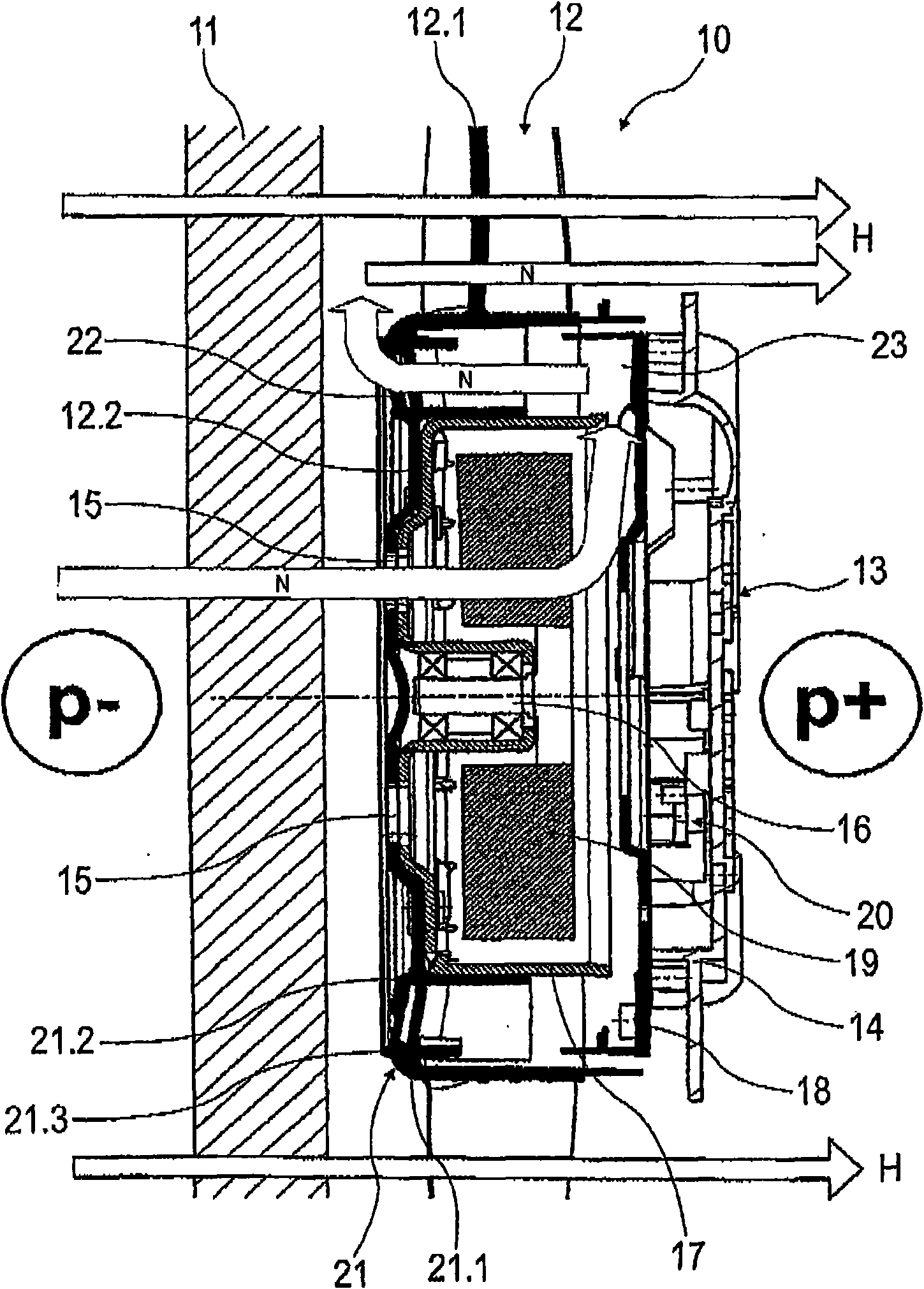
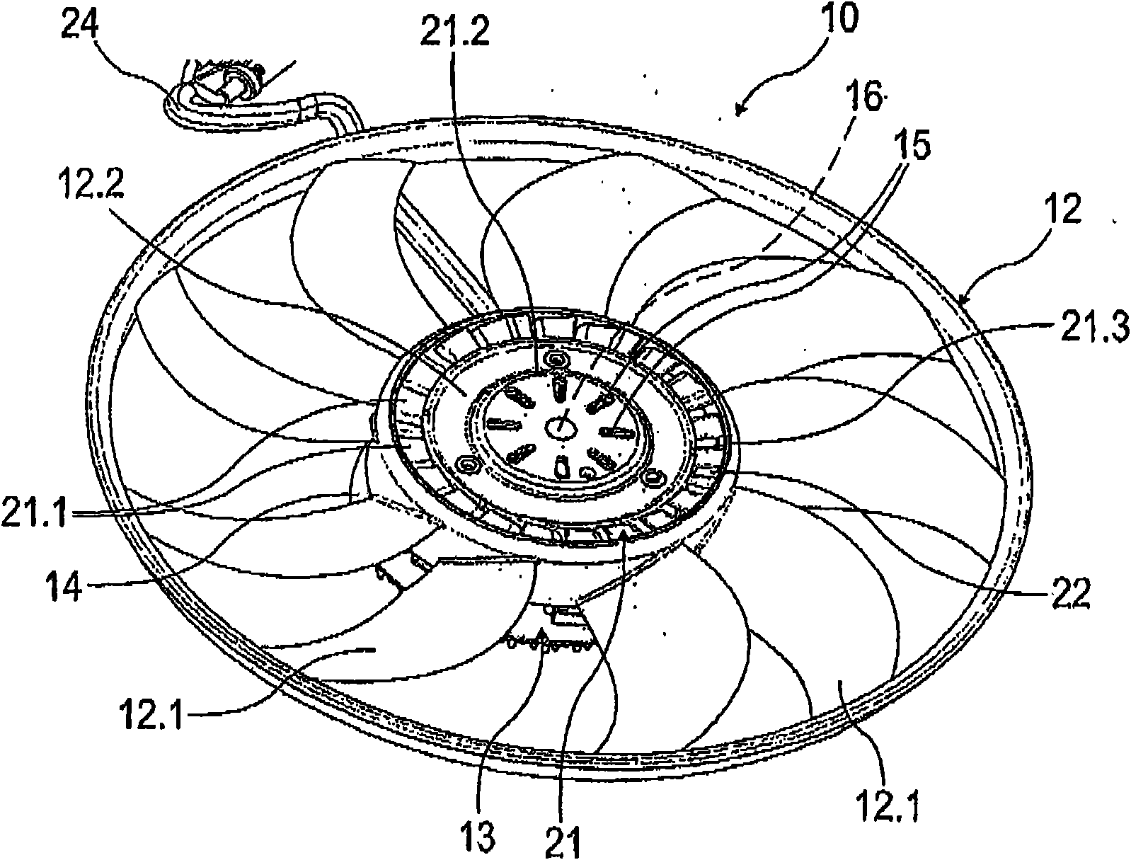
[0018] exist figure 1 The middle area of ​​the axial flow fan 10 partially shown by dotted lines is shown in , the axial flow fan has a horizontal rotation axis and a vertical rotation plane, and the axial flow fan is arranged on the automobile radiator at small intervals After the broad side of 11. In this case, the plane of rotation of the axial fan 10 runs substantially parallel to the rear broad side of the heat sink 11 since it is designed as a parallelepiped cross-flow heat sink.

[0019] The usual function of the axial fan 10 is that, when there is not enough traveling relative air flow through the radiator 11, the circulation of the radiator 11 sufficient to cool the radiator medium is achieved by means of the cooling air flow generated by the rotation of the fan wheel 12, The flow direction of the cooling air flow is consistent with the direction of the driving relative air flow. For this purpose, the fan wheel 12 is rotationally driven counterclockwise by means of ...


PUM


Abstract

The invention relates to an axial fan for a vehicle radiator, wherein the fan wheel feeding the main air flow is driven by means of a hub motor that is centrally rotationally coupled to the same. The vehicle radiator is disposed on the intake side of the fan wheel, the hub motor is cooled during its operation by means of an auxiliary air flow, and the cooling air flow of the hub motor flows out of an air outlet port positioned on the intake side of the fan wheel in the hub region. In order to provide an adequate air flow for the cooling of the hub motor, while avoiding a significant reduction in the fan's efficiency ratio, an air deflector device is associated with the hub motor, through which the majority of the hub motor's cooling air flow must pass, and the cooling air flow passing through the air deflection device is directed out of the air outlet port, while avoiding interferences of the main air flow delivered by the fan wheel.

Description

technical field [0001] The invention relates to an axial fan for a motor vehicle radiator according to the preamble of claim 1 . Background technique [0002] For drives of such axial fans, which can generate cooling air flow in cross-flow radiators of internal combustion engines of vehicles, for example, electric motors are used in particular, which have a maximum power output at high ambient temperatures and are therefore Also has the highest self-heating. In particular when electric fans have a large hub diameter and are provided with an axial fan wheel on the suction side, the problem arises that the air is only insufficiently flowed through the electric motor which is usually arranged in the hub. It is known in this respect to guide the cooling air flow axially through the hub motor in order to reduce the self-heating of the electric motor and thus increase the service life while increasing the performance. If one provides corresponding through-holes for the cooling a...

Claims


Application Information

Patent Timeline
IPC IPC(8): F04D25/08
CPCF04D25/082F04D29/5806
Inventor 卡尔-海因茨·弗莱施曼斯特凡·博格亚历山大·加斯
Owner 博泽汽车部件有限公司及两合公司,乌茨堡
Why Eureka
Try Eureka