Circular arc or circular gantry structure for machine tool, robot and mechanical measuring machine

A robot, arc-shaped technology, applied in mechanical measuring devices, mechanical devices, manipulators, etc., can solve problems such as good rigidity, achieve good accuracy, simplify gantry structure, and increase structural strength.

Inactive Publication Date: 2010-01-06
周刚
View PDF0 Cites 10 Cited by
  • Summary
  • Abstract
  • Description
  • Claims
  • Application Information

AI Technical Summary

Problems solved by technology

The machine tool with this structure can also realize quadrant movement, the angle can exceed 180 degrees, the cantilever is very short, and the rigidity is good; the machine tool with this structure can overcome the complexity of the control, operation, programming, manufacturing, measurement and correction of the parallel mechanism machine tool; The machine tool structure of arc or circular gantry is applied in the grinding machine to fix the workpiece, without the disadvantage of strong centrifugal force when the workpiece rotates, and the grinding head makes circular motion relative to the workpiece, which improves the machining accuracy and efficiency

Method used


Image

  • Circular arc or circular gantry structure for machine tool, robot and mechanical measuring machine
  • Circular arc or circular gantry structure for machine tool, robot and mechanical measuring machine
  • Circular arc or circular gantry structure for machine tool, robot and mechanical measuring machine

Examples


Embodiment Construction

[0023] The present invention discloses 3 embodiments, which are described as follows in conjunction with the accompanying drawings:

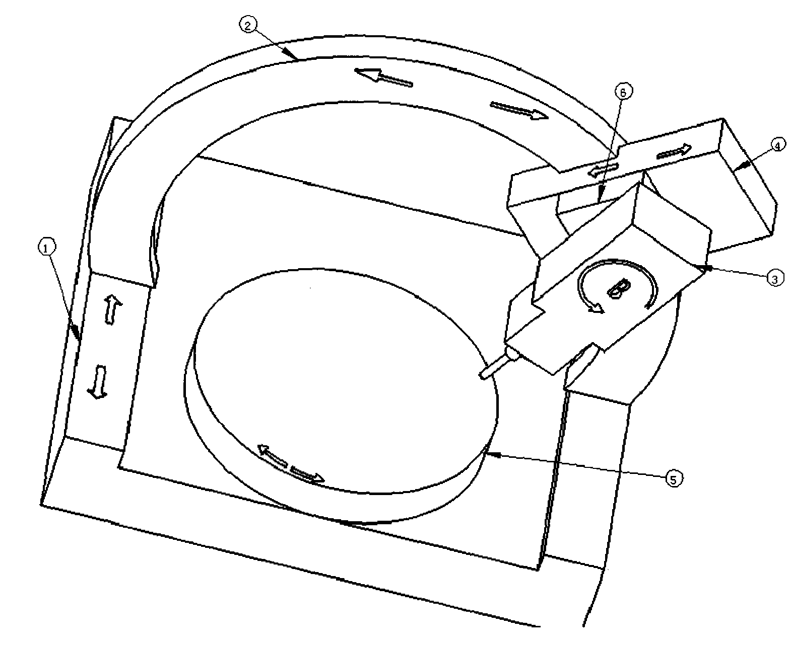
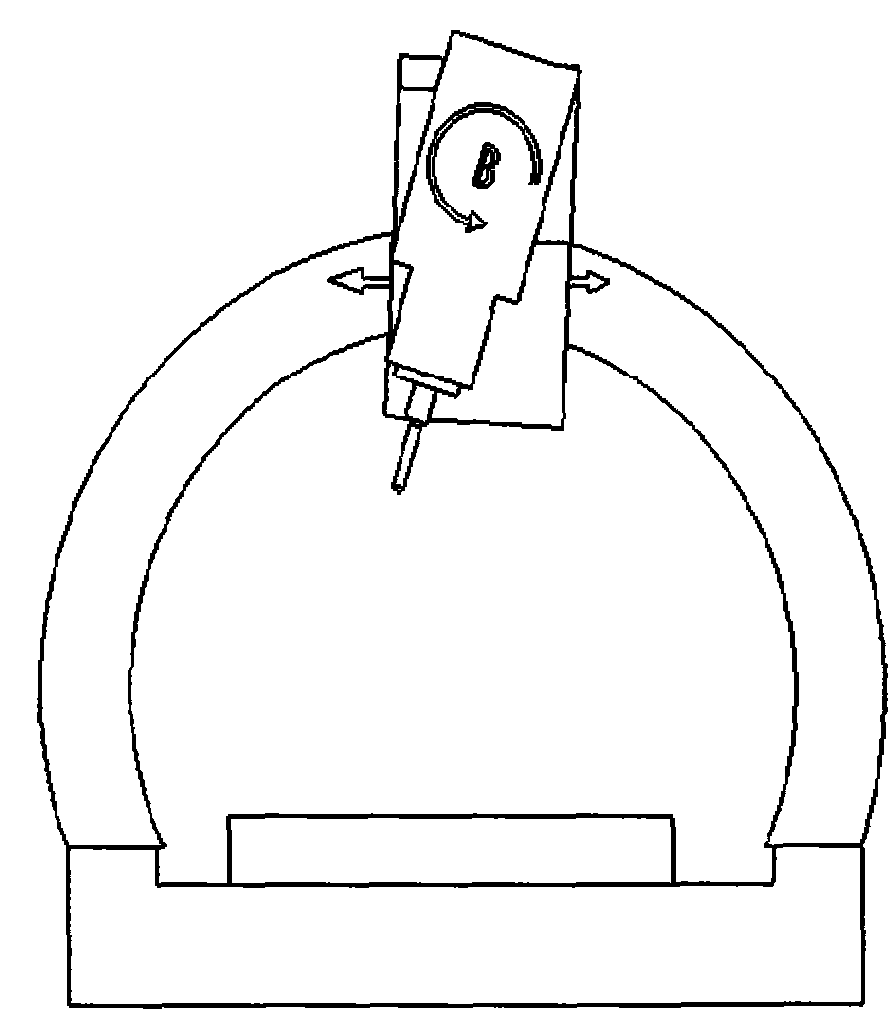
[0024] 1. In figure 1 In the shown embodiment, the main shaft and the tool (3) are connected in series with the circular arc gantry structure (2) through the small sliding seat (6) and the large sliding seat (4), and the main shaft (3) can perform an arc motion of more than 180 degrees ( figure 2 image 3 ); the main shaft (3) performs rotary motion relative to the small slide (6), the small slide (6) moves up and down relative to the large slide (4), and the large slide (4) conforms to the guide rail of the arc gantry structure (2) Arc motion. The corresponding processing motion can be obtained by controlling each component to do a single or joint action.

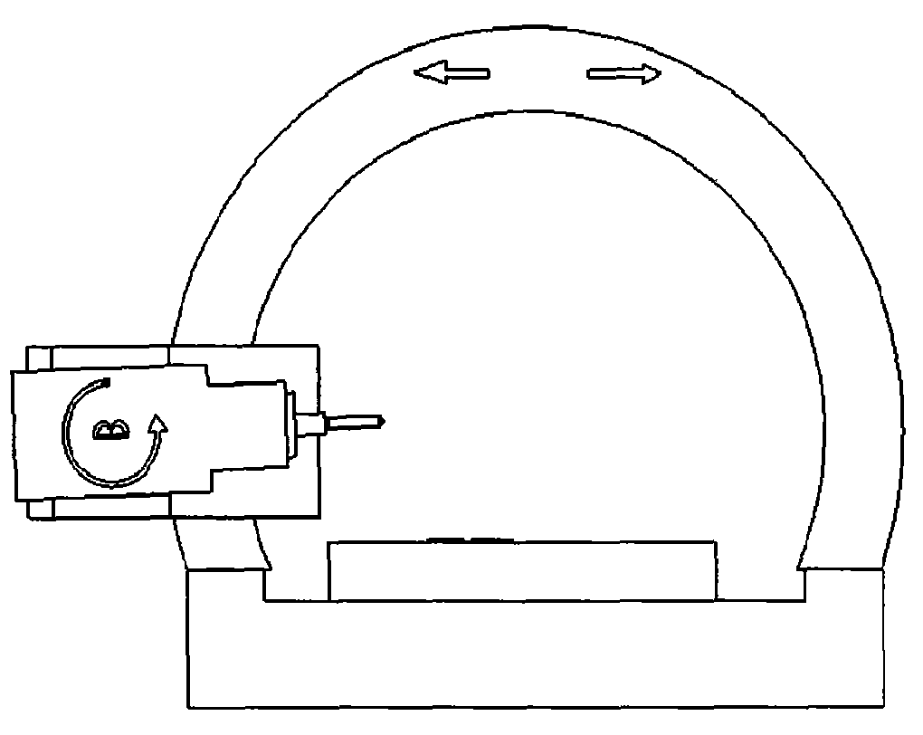
[0025] 2. In Figure 4 In the shown embodiment, the main shaft and the tool (4) are connected in series with the guide rail of the circular gantry structure (1) through the small slidin...


PUM


Abstract

The invention relates to a circular arc or circular gantry structure for a machine tool, a robot and a mechanical measuring machine. A traditional track gantry frame comprising three components (one transverse beam and two upright posts) is designed and manufactured into a circular arc or circular gantry structure component, then the circular arc or circular gantry structure component is connected with a main shaft, a main shaft box or other movement components in series, and the main shaft, the main shaft box or other movement components are controlled to make required relevant movement and direction movement on a track of the circular arc or circular gantry structure component, thereby three-dimensional translation and three-dimensional movement output can be realized. The structure can be used as the basis of the actuating mechanisms of the machine tool, the robot and the mechanical measuring machine.

Description

Technical field [0001] The invention relates to the fields of machine tools, robots and coordinate measuring machines, in particular, it can be used for arc or circular gantry structures of numerically controlled machine tools, handling robots and mechanical measuring machines. Background technique [0002] Currently known lathes and machinery have the following types in structure: [0003] 1. The gantry structure of the known CNC machine tools is a square door-shaped series structure, and is composed of 3 parts (2 columns, 1 beam) to form a gantry, and the 3 parts are used for manufacturing and assembly. , inspection and other production links have brought many difficulties; a machine tool characterized by a gantry is composed of 3 parts (2 columns, 1 beam), especially a gantry machining center, which requires more than two axes when doing arc machining movements Linkage interpolation can only be completed, and the trajectory of the machine tool (3-axis gantry machining ce...

Claims


Application Information

Patent Timeline
Patent Type & Authority Applications(China)
IPC IPC(8): B23Q1/01B25J19/00G01B5/008
CPCB23Q2210/006B23Q1/012
Inventor 周刚
Owner 周刚
Why Eureka
Try Eureka