Transformer neutrality point combination electric device

A technology for transformer neutral point and combined electrical appliances, which is applied in the direction of emergency protection circuit devices, grounding devices, electrical components, etc. It can solve problems such as unsatisfactory contact stability, electrical equipment safety threats, high power frequency overvoltage of power grid, etc., to achieve The effect of reducing device cost, small footprint, and small installation workload

Inactive Publication Date: 2010-01-06
上海安越电气工程技术有限公司
View PDF0 Cites 10 Cited by
  • Summary
  • Abstract
  • Description
  • Claims
  • Application Information

AI Technical Summary

Problems solved by technology

[0005] 2. When this kind of power grid accidentally forms a local ungrounded power grid for some reason, and a single-phase ground fault occurs, under this abnormal working condition, the power grid may generate high power frequency overvoltage, which affects the safety of electrical equipment in the power grid. Therefore, according to the regulations of DL / T620-1997, the neutral point of the ungrounded transformer should be equipped with a rod-shaped air protection gap, also known as a rod gap.
Therefore, the overall weight is large and consumes a lot of porcelain resources
[0013] 3. The longitudinal length of the entire device is long after combination, which is not suitable for indoor and underground stations such as 110kV
[0014] 4. The GW13 series neutral point isolating switch is a double-rotary arm coupling structure, and the contact stability is not ideal.
[0015] 5. When the longitudinal arrangement length of the equipment reaches more than 3.5m, a double-pillar installation structure must be adopted, and the cost of foundation and pillars is high

Method used


Image

  • Transformer neutrality point combination electric device
  • Transformer neutrality point combination electric device
  • Transformer neutrality point combination electric device

Examples


Embodiment Construction

[0058] Hereinafter, the transformer neutral point combined electrical device of the present invention will be described in detail with reference to the accompanying drawings.

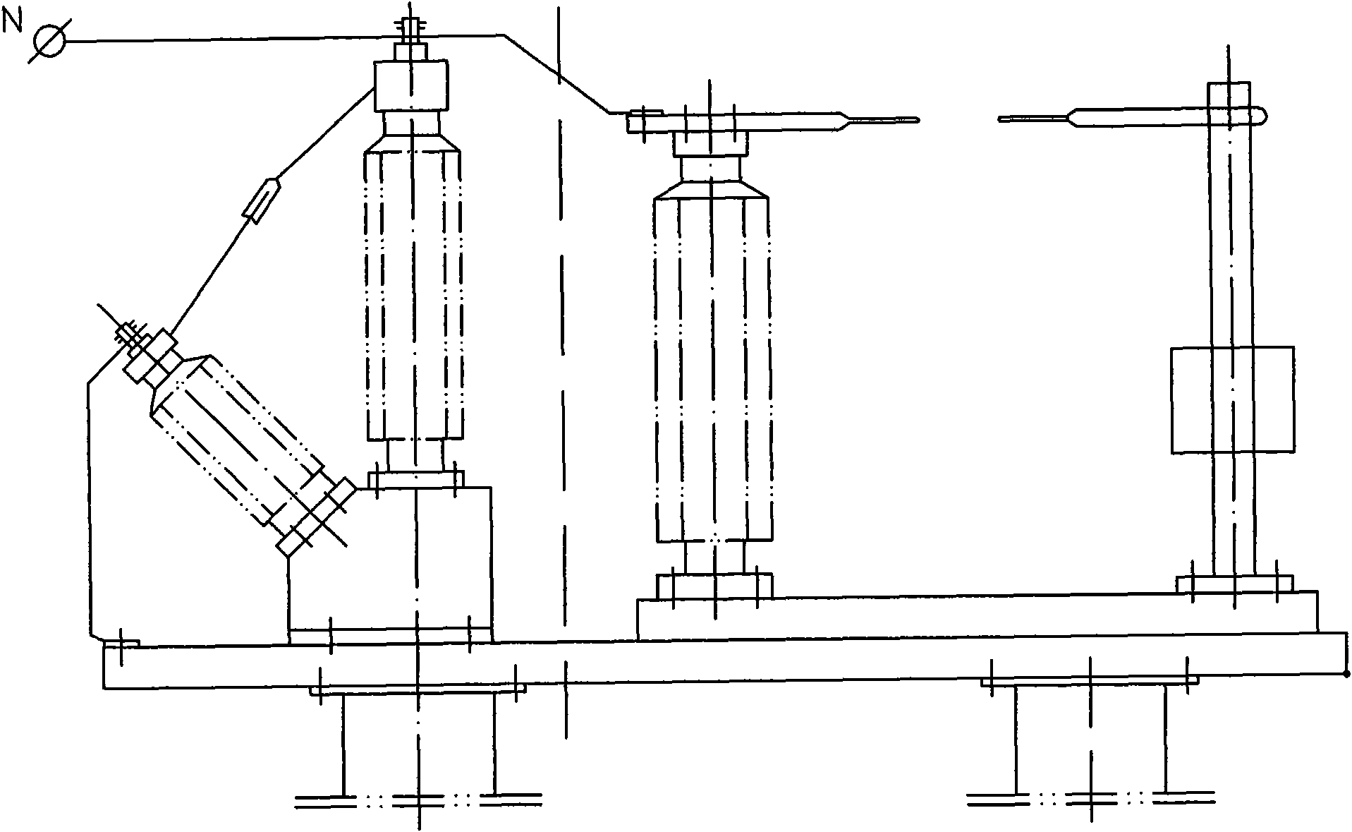
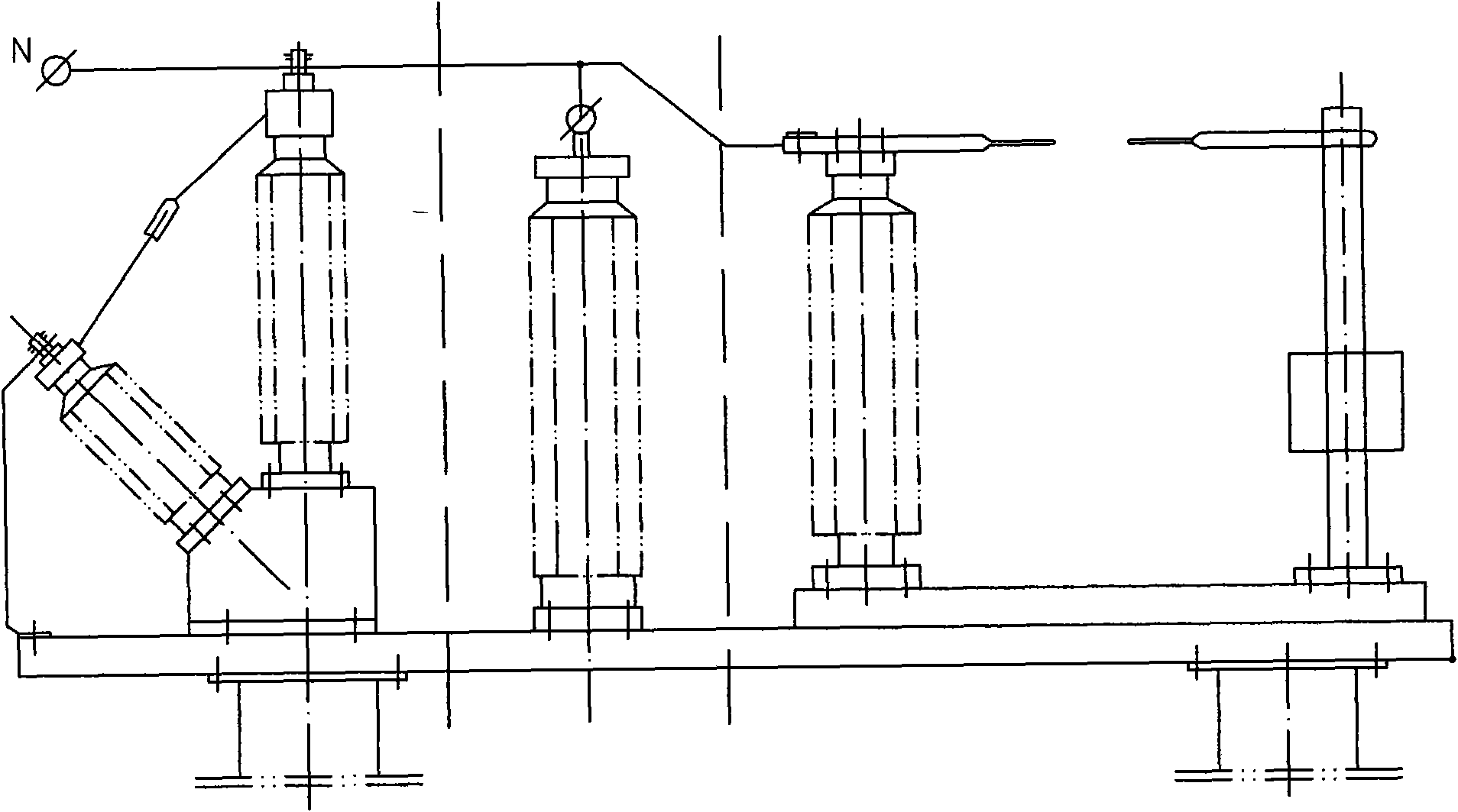
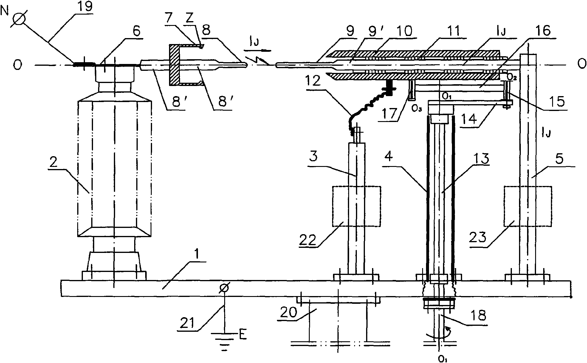
[0059] Aiming at the problems of the existing transformer neutral point equipment and the functional characteristics of each equipment, the present invention proposes a new transformer neutral point combined electrical device. The core of the present invention is to combine the neutral point isolation switch with the protection gap J Integration, and install all components on the same base 1, such as image 3 , Figure 4 Shown.

[0060] The invention includes a base 1, an insulating support column 2, a high-voltage electrode 8, a ground electrode 9, a fixed contact 7, a ground sleeve 10, a ground column 5, a rotating shaft 13, a ground guide column 3, and the like.

[0061] On the base 1, an insulating support column 2, a grounding guide column 3, a shaft column tube 4 and a grounding column 5 are vertically f...


PUM


Abstract

The invention discloses a transformer neutrality point combination electric device comprising a base (1), wherein the base (1) is grounded and provided with an insulating support post (2), and the insulating support post (2) is provided with a horizontal high-voltage arm (8'), and the horizontal high-voltage arm (8') is connected with a transformer neutrality point (N) and provided with a fixed contact (7); the base (1) is also provided with a grounding post (5), the grounding post (5) is provided with a horizontal grounding arm (9') which is sleeved with a grounding sleeve pipe (10), an insulating bushing is arranged between the grounding arm (9') and the grounding sleeve pipe (10), and the grounding sleeve pipe (10) can slide relative to the grounding arm (9'); the high-voltage arm (8') is provided with a high-voltage electrode (8), the grounding arm (9') is provided with a grounding electrode (9), the high-voltage electrode (8) and the grounding arm (9') are coaxial, oppositely arranged and form a protection gap (J), and the grounding sleeve pipe (10) is provided with a division and combination adjusting device. The invention has simple structure and high aggregation degree.

Description

Technical field [0001] The invention relates to the field of power transmission technology, and is a transformer neutral point combined electrical device that combines the functions of each single equipment required by the current 110kV and 220kV transformer neutral points into an integrated device. Background technique [0002] According to the People’s Republic of China Electric Power Industry Standard DL / T620-1997 "Overvoltage Protection and Insulation Coordination for AC Electrical Installations", 110kV and 220kV power grids (hereinafter referred to as grids) are effectively grounded grids, that is, the neutral point of the grid during actual operation The voltage to the ground (that is, the earth) is "0" or close to "0". The neutral point of this type of power grid must be effectively grounded. The neutral point of the power grid is grounded by the neutral point of the transformer in the power grid. In actual operation, the selective grounding operation mode is adopted, that...

Claims


Application Information

Patent Timeline
Patent Type & Authority Applications(China)
IPC IPC(8): H02B1/16H01R4/66H02H7/04
Inventor 杨逊弘
Owner 上海安越电气工程技术有限公司
Why Eureka
Try Eureka