Miniature power generating device based on piezoelectric crystal frequency converting mechanism
A frequency conversion, piezoelectric crystal technology, applied in the direction of piezoelectric effect/electrostrictive or magnetostrictive motors, generators/motors, electrical components, etc., can solve the existence of electromagnetic interference, low output voltage, high frequency and other problems, to achieve the effect of reliable operation, high output voltage and high energy density
- Summary
- Abstract
- Description
- Claims
- Application Information
AI Technical Summary
Problems solved by technology
Method used
Image

Examples
Embodiment 1
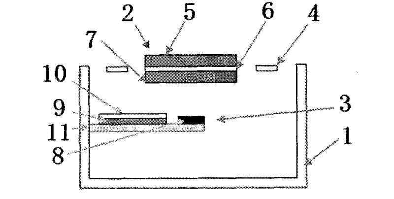
[0023] Such as figure 1 , figure 2 and image 3 As shown, this embodiment includes: a base body 1, a frequency conversion mechanism 2 and a set of power generation mechanisms 3, wherein: the frequency conversion mechanism 2 is fixedly arranged on the top of the base body 1, and the power generation mechanism 3 is fixedly arranged inside the base body 1 and connected to the base body 1 In contact with each other, the frequency conversion mechanism 2 and the power generation mechanism 3 are parallel to each other.
[0024] The base 1 is a rectangular structure without a top, made of aluminum material, wherein the bottom surface is a square, the side length is 3 mm, the height is 1.75 mm, and the base body thickness is 200 microns;
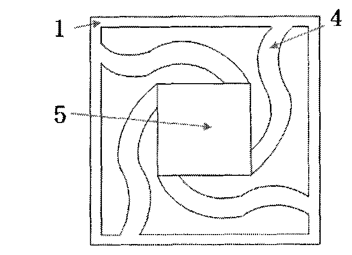
[0025] Such as figure 1 and figure 2 As shown, the frequency conversion mechanism 2 includes: four upper planar springs 4, an upper surface permanent magnet 5, a permanent magnet support platform 6 and a lower surface permanent magnet 7, wherei...
Embodiment 2
[0037] Such as Figure 4a and 4b As shown, this embodiment includes: a base body 1, a frequency conversion mechanism 2 and 4 sets of power generating mechanisms 3 with the same structure, wherein: the frequency conversion mechanism 2 is fixedly arranged on the top of the base body 1, and the four sets of power generation mechanisms 3 are fixedly arranged on the top of the base body 1 The four inner sides are in contact with the substrate 1, and the frequency conversion mechanism 2 and the power generation mechanism 3 are parallel to each other.
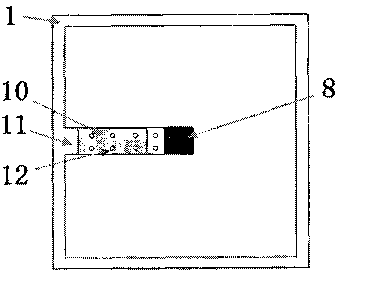
[0038] The 4 sets of generating mechanisms 3 in this embodiment are the same as those in Embodiment 1, and all include: a soft magnetic metal layer 8, a piezoelectric material 9, a metal electrode 10, and an elastic support layer 11, wherein: one end of the elastic support layer 11 is fixedly arranged Inside the base body 1, the upper surface of the other end of the elastic support layer 11 is provided with a soft magnetic metal laye...
Embodiment 3
[0040] Such as Figure 5a and Figure 5b As shown, this embodiment includes: a base body 1, a frequency conversion mechanism 2 and a set of power generation mechanisms 3, wherein: the frequency conversion mechanism 2 is fixedly arranged on the top of the base body 1, and four sets of power generation mechanisms 3 are fixedly arranged inside the base body 1. The sides are in contact with the substrate 1, and the frequency conversion mechanism 2 and the power generation mechanism 3 are parallel to each other.
[0041] Such as Figure 5b As shown, the power generating mechanism 3 in this embodiment includes: a soft magnetic metal layer 8, a piezoelectric material 9, a metal electrode 10, and an elastic support layer 11, wherein: the elastic support layer 11 is a swastika structure, and the end of the elastic support layer 11 Fixedly arranged inside the base body 1, the upper surface of the center of the elastic support layer 11 is provided with a soft magnetic metal layer 8, the ...
PUM
 Abstract
Description
Claims
Application Information
 - R&D
- Intellectual Property
- Life Sciences
- Materials
- Tech Scout
- Unparalleled Data Quality
- Higher Quality Content
- 60% Fewer Hallucinations
Browse by: Latest US Patents, China's latest patents, Technical Efficacy Thesaurus, Application Domain, Technology Topic, Popular Technical Reports.
© 2025 PatSnap. All rights reserved.Legal|Privacy policy|Modern Slavery Act Transparency Statement|Sitemap|About US| Contact US: help@patsnap.com