Control of a plurality of plug coils via a single power stage

A technology for controlling signal and frequency, applied in spark ignition controller, ignition controller, spark ignition device, etc., can solve the problems of huge volume, limiting development potential, hindering ignition installation, etc.

Active Publication Date: 2010-01-06
RENAULT SA
View PDF5 Cites 3 Cited by
  • Summary
  • Abstract
  • Description
  • Claims
  • Application Information

AI Technical Summary

Problems solved by technology

[0017] Such a configuration therefore relies on as many amplification paths as there are controlled plug coils, thus limiting the development potential of this type of motor vehicle ignition by plasma generation, partly because of this installation under the hood The resulting bulkiness, also because of the cost of the installation, has proven to be a hindrance to the installation of this type of ignition on mass-produced vehicles

Method used


Image

  • Control of a plurality of plug coils via a single power stage
  • Control of a plurality of plug coils via a single power stage
  • Control of a plurality of plug coils via a single power stage

Examples


Embodiment Construction

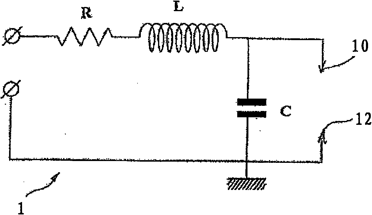
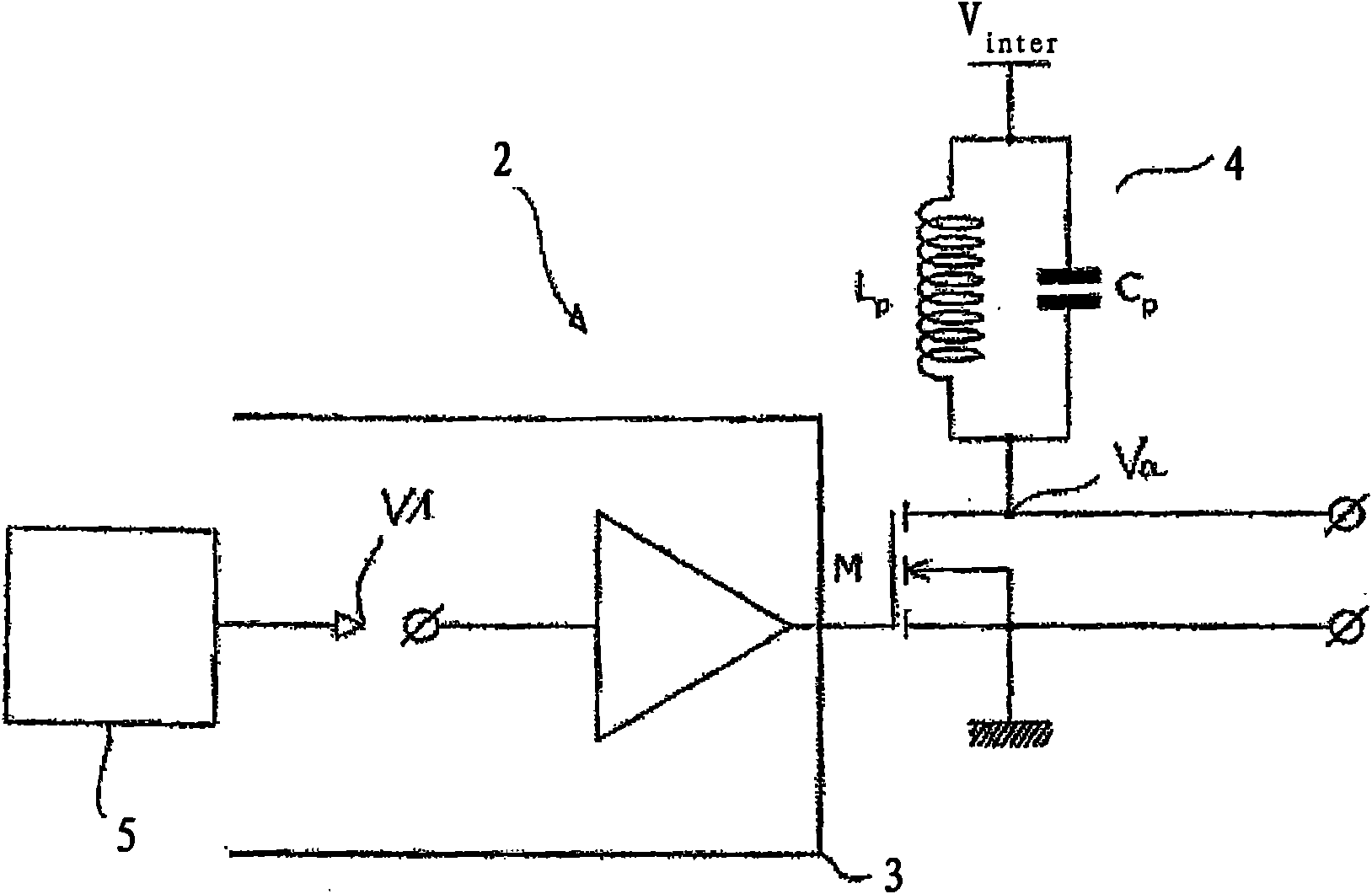
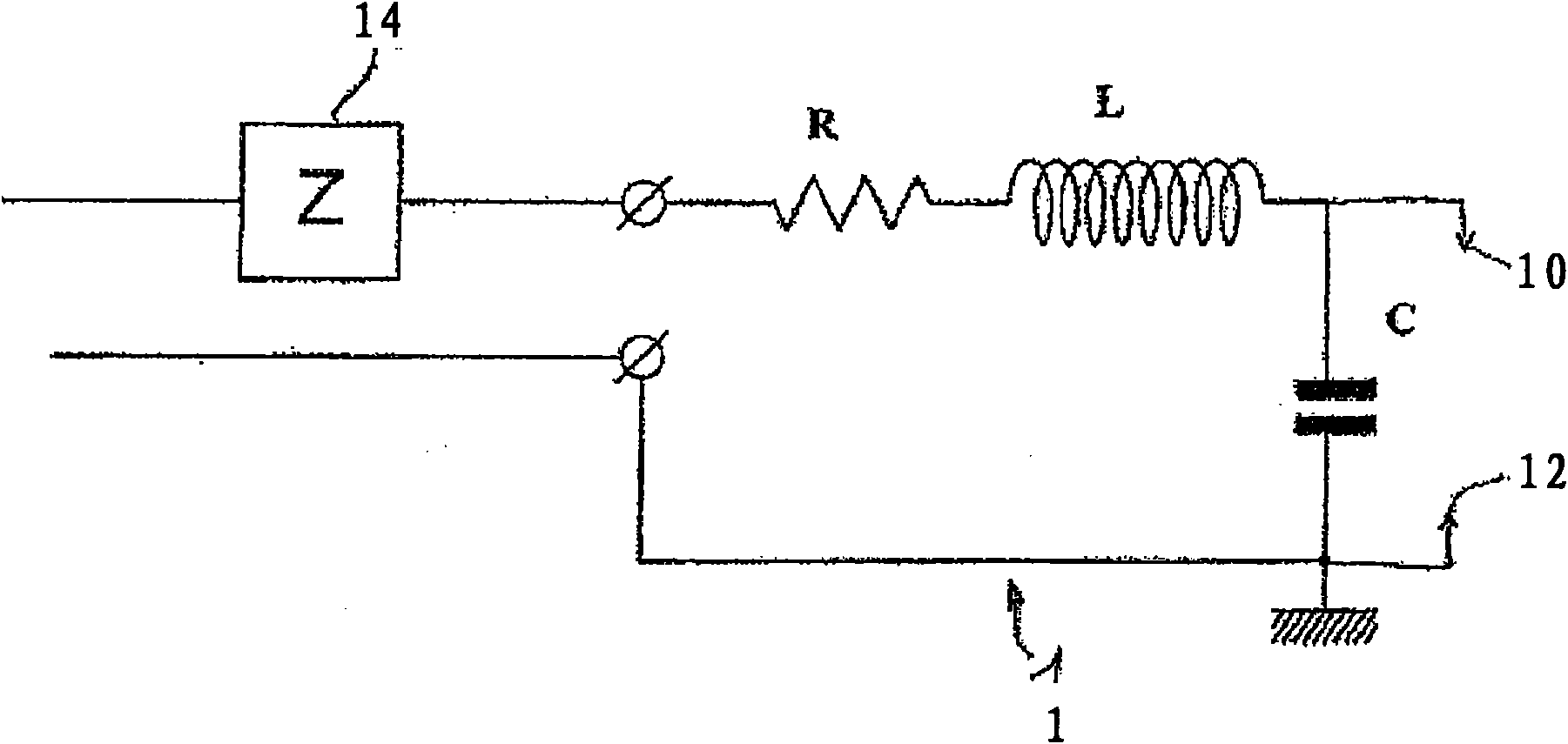
[0042] Therefore, the object of the present invention is to control a plurality of plug-coil type plasma generating circuits by using one amplification path, in other words, by using a figure 2 A power supply circuit of the class E power amplifier type described in , selectively powers the plurality of plasma generating circuits connected in parallel to the output of this one power supply circuit.

[0043] The principle behind this particular assembly is to exploit the self-resonant frequency of the respective plasma generating circuit connected to the output of the power supply circuit at the high voltage and high frequency control level generated by the power supply circuit.

[0044]Indeed, it appears that a reasonable distribution of the resonant frequencies of the plasma generating circuits makes it possible to naturally determine the desired transfer of power from the power supply circuit to one or the other of the plasma generating circuits. Thus, depending on whether th...


PUM


Abstract

The invention relates to a radiofrequency plasma generating device that comprises: a supply circuit (2) including a switch (M) controlled by a control signal (V1) for applying a voltage (Vinter) on an output of the control circuit at a control frequency; at least two plasma-generating circuits (BB1, BB2, BB3, BB4) connected in parallel at the output of the supply circuit, each circuit having its own resonance frequency and being capable of generating plasma when a high voltage level is applied to the output of the supply circuit at a frequency substantially equal to the resonance frequency of the plasma generation circuit; and a supply control device (5) for determining the control frequency from the resonance frequencies (F1, F2, F3, F4) of the plasma generation circuits in order to selectively control each circuit according to the control frequency used.

Description

technical field [0001] The present invention generally relates to a plasma generation system between two electrodes of a plug, in particular for controlled radio frequency ignition of a gaseous mixture in a combustion chamber of an internal combustion engine. Background technique [0002] For this application to plasma-generating motor vehicle ignition, a plasma-generating circuit with a plugcoil is used to generate a multiple-filament discharge between its electrodes, making it possible to start the Combustion of the mixture. The multi-spark plug is described in detail in the following patent applications in the name of the applicant: FR 03-10766, FR 03-10767, FR 03-10768. [0003] Conventionally, such a plug coil is modeled by a resonator 1 whose resonance frequency Fc is greater than 1 MHz, typically close to 5 MHz. A resonator consists of a resistor R, an inductor L and a capacitor C connected in series. The ignition electrodes 10 and 12 of the plug coil are connected...

Claims


Application Information

Patent Timeline
Patent Type & Authority Applications(China)
IPC IPC(8): F02P9/00F02P23/04F02P17/12
CPCF02P23/045F02P9/007F02P3/01F02P7/02F02P9/00F02P17/12F02P23/04
Inventor P·巴罗索C·努瓦尔N·梅西蒂
Owner RENAULT SA
Why Eureka
Try Eureka