Rotary piston engine

一种旋转活塞、发动机的技术,应用在内燃活塞发动机、燃烧发动机、机器/发动机等方向,能够解决不涉及、产生燃料混合物导出废气、难运动过程精确控制等问题,达到增大泵功率、提高驱动力矩的效果

Inactive Publication Date: 2012-01-25
海因茨·劳巴彻
View PDF10 Cites 1 Cited by
  • Summary
  • Abstract
  • Description
  • Claims
  • Application Information

AI Technical Summary

Problems solved by technology

It is difficult to achieve precise control of the motion process through the motion path
Furthermore, the design requires complex measures for controlling the combustion, creating the fuel mixture and discharging the exhaust gases
It is difficult to properly construct such an internal combustion engine especially at slow motion and high torque
Therefore, this internal combustion engine is not currently involved

Method used


Image

  • Rotary piston engine
  • Rotary piston engine
  • Rotary piston engine

Examples


Embodiment Construction

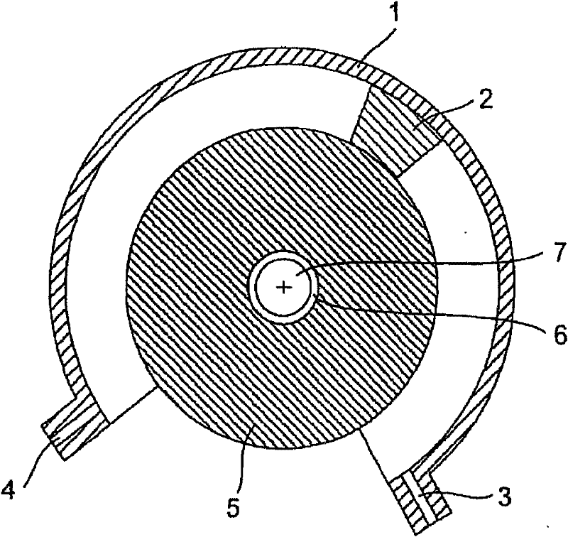
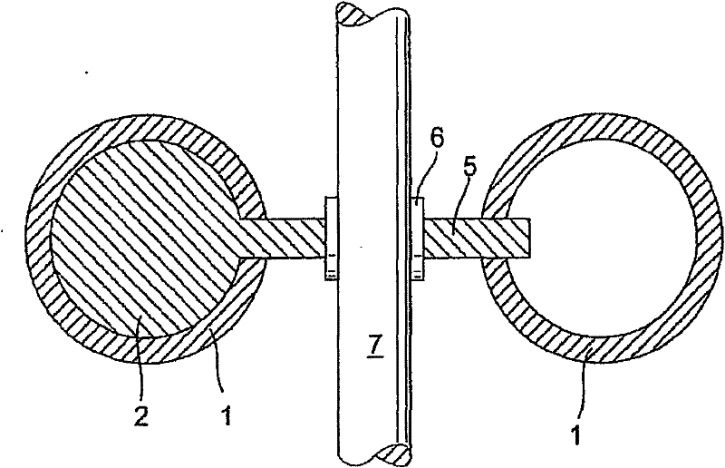
[0039] figure 1 A schematic illustration of a section through a rotary piston engine perpendicular to a rotating body in the form of an axis 7 is shown. The piston 2 is guided in an annular channel 1 extending along a subcircle at an angle greater than 180° (for example a circular cylinder) and the movement of the piston is guided through the sleeve by means of a lever 5, for example designed as a circular disc 6 is transferred to axis 7.

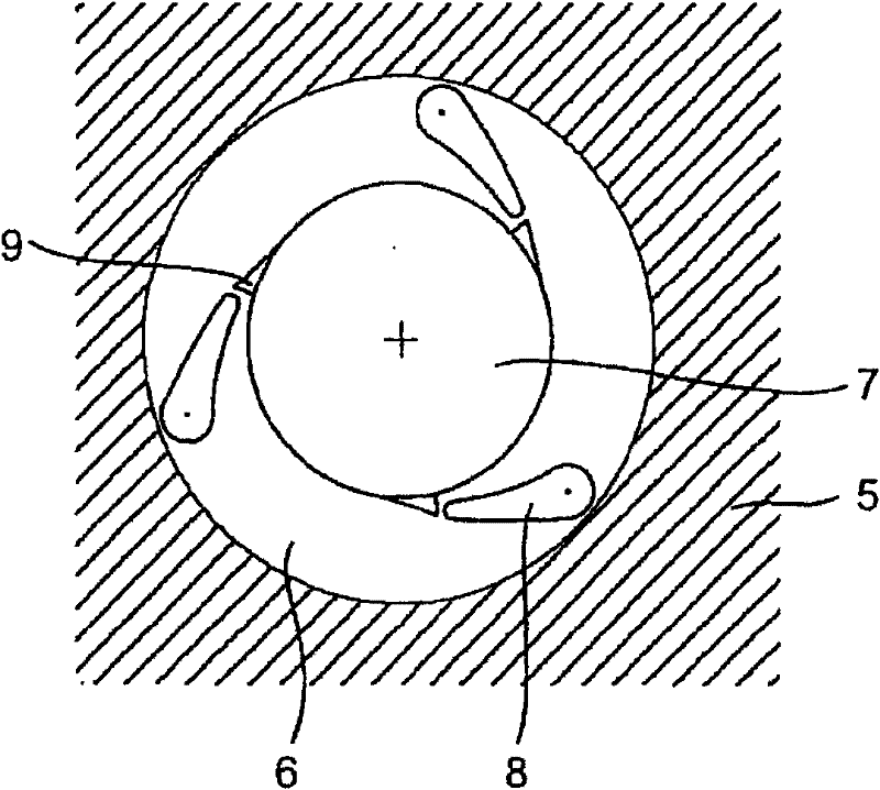
[0040] The piston 2 is moved, for example, as a drive element by pumping in a preferably incompressible fluid via the corresponding fluid connection 3 or 4 or by discharging the fluid via the other fluid connection 4 or 3 . On the shaft 7 is provided a sleeve 6 for connection between the lever 5 and the shaft 7, which can be designed in various forms, for example, for transmitting torque to the shaft 7 in one direction and idling in the other direction or with to transmit torque in both directions. Considerable angular ranges (for examp...


PUM


Abstract

The invention relates to a planetary rotation machine comprising at least one ring channel (1) which is curved along an at least partial arc and contains a piston (2) that can be moved in a fluid generating a movement, said piston being coupled to a rotary body coaxially arranged by means of a lever (5) by the rotational axis thereof. A stable structure able to transmit high torques is obtained by guiding the lever (5) through a gap created in the wall of the ring channel (1) in the direction of displacement of the piston (2), in the radial direction away from the piston (2) in a sealed manner.

Description

technical field [0001] The invention relates to a rotary piston engine with at least one annular channel curved at least partially in the shape of a circular arc, in which a piston is mounted movably in a motion-transmitting fluid flow through a fluid connection and through In the fluid flowing out of another fluid interface, the piston is connected with the rotating body concentric with the circular arc and the rotation axis is coaxially arranged with the circular arc through the lever, wherein the lever passes through the wall of the annular passage along the moving direction of the piston The gap between the relative rolling element seals. Background technique [0002] A rotary piston engine of this type is disclosed in German utility model DE9103452U1. In this known rotary piston engine in the form of a hydraulic engine, a piston connected to the drive rotates in an annular housing by hydraulic loading. In this case, the tubular interior of the housing is supplied with...

Claims


Application Information

Patent Timeline
Patent Type & Authority Patents(China)
IPC IPC(8): F02B53/14F04C9/00F04C15/00
CPCY02T10/17F04C15/0007F04C9/002F04C2240/30F04C15/00F04C9/00
Inventor 海因茨·劳巴彻
Owner 海因茨·劳巴彻
Why Eureka
Try Eureka