
Liquid crystal display panel and liquid crystal display device

A liquid crystal display panel and liquid crystal display device technology, applied in static indicators, nonlinear optics, instruments, etc., can solve problems such as uneven coverage of the liquid crystal molecule dumping area, uneven number of liquid crystal molecules, and uneven pixel brightness. Achieve the effect of reducing the defects of dark spots, reducing image sticking, and reducing abnormal alignment

Inactive Publication Date: 2012-06-20
INNOLUX CORP
View PDF0 Cites 0 Cited by
  • Summary
  • Abstract
  • Description
  • Claims
  • Application Information

AI Technical Summary

Problems solved by technology

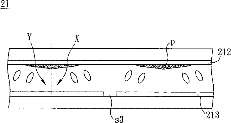
[0006] However, due to the flattening of the protruding portion p, the liquid crystal molecules in each pixel of the liquid crystal display panel 21, which are distinguished by the vertices of the protruding portion p, will fall into regions (domain, such as figure 2 X and Y shown) create an ambiguous situation
In addition, the slight deviation of the apex p of the protruding part caused by the error in the manufacturing process will make the coverage of the liquid crystal molecule dumping area in each pixel uneven.
The above-mentioned problems will cause the number of liquid crystal molecules in each area to be uneven, so when the liquid crystal display panel 21 is viewed sideways at a certain angle, uneven pixel brightness will occur.

Method used


Image

  • Liquid crystal display panel and liquid crystal display device
  • Liquid crystal display panel and liquid crystal display device
  • Liquid crystal display panel and liquid crystal display device

Examples


Embodiment Construction

[0046] A liquid crystal display panel and a liquid crystal display device according to preferred embodiments of the present invention will be described below with reference to related drawings, wherein the same components are denoted by the same reference numerals.

[0047] first preferred embodiment

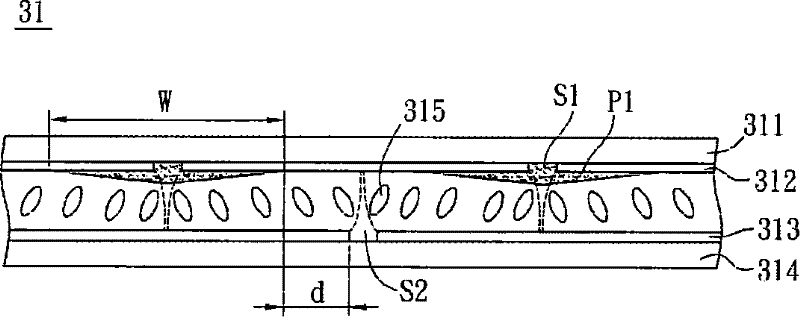
[0048] Please refer to image 3 As shown, a liquid crystal display panel 31 of the first preferred embodiment of the present invention includes a first substrate 311, a first electrode layer 312, a second electrode layer 313, a second substrate 314, and a liquid crystal layer 315 and A plurality of first protrusions P1. The liquid crystal display panel 31 may be a multi-domain vertical alignment (MVA) liquid crystal display panel.

[0049]The first electrode layer 312 is a transparent electrode layer, which is formed in a way such as but not limited to sputtering (sputter), and the material is selected from indium tin oxide (indium tin oxide, ITO), indium zinc oxide (indium ...


PUM

PropertyMeasurementUnit
widthaaaaaaaaaa

Abstract

The invention discloses a liquid crystal display panel, which comprises a first substrate, a second substrate, a first electrode layer, at least one first lug boss, a second electrode layer and a liquid crystal layer. The first electrode layer is arranged on the first substrate and is provided with at least one first slit pattern. The first lug boss covers the first slit pattern. The second electrode layer is arranged on the second substrate, is opposite to the first electrode layer and is provided with at least one second slit pattern. The first and second slit patterns are in staggered arrangement with each other. The liquid crystal layer is arranged between the first electrode layer and the second electrode layer. The invention also discloses a liquid crystal display device.

Description

technical field [0001] The present invention relates to a liquid crystal display panel and a liquid crystal display device, in particular to a multi-domain vertical alignment (MVA) liquid crystal display panel and a liquid crystal display device. Background technique [0002] With the advent of the digital age, the technology of liquid crystal display devices has also grown rapidly and has become an indispensable electronic product. Relatively, the technical and functional requirements of liquid crystal display devices are getting higher and higher, especially light, thin, short, The liquid crystal display device with characteristics such as small size plays a very important role. At present, liquid crystal display devices have been widely used in various electronic products, such as mobile phones, personal digital assistants (Personal Digital Assistant, PDA) and notebook computers (Notebook, NB), etc., and reducing the reaction time of liquid crystal molecules is One of th...

Claims


Application Information

Patent Timeline
Patent Type & Authority Patents(China)
IPC IPC(8): G02F1/1343G02F1/133
Inventor 谢明峰
Owner INNOLUX CORP
Learn More