Controller area network (CAN) bus system and application layer communication method in same

A technology of CAN bus and communication method, which is applied in the field of CAN bus, can solve the problems of long cycle, inconvenient modification and transplantation, and high cost, and achieve the effects of strong applicability, easy promotion and transplantation, and simple use

Active Publication Date: 2011-11-23
北京和利时电机技术有限公司
View PDF0 Cites 0 Cited by
  • Summary
  • Abstract
  • Description
  • Claims
  • Application Information

AI Technical Summary

Problems solved by technology

The use of complex general-purpose protocols will generally lead to high cost and long cycle of CAN bus application design and development; the application of specific dedicated protocols has very large limitations, and the application code contains very specific application layer information definitions, modifications and Porting is very inconvenient

Method used


Image

  • Controller area network (CAN) bus system and application layer communication method in same
  • Controller area network (CAN) bus system and application layer communication method in same
  • Controller area network (CAN) bus system and application layer communication method in same

Examples


Embodiment 1

[0046] Embodiment 1, an application layer communication method in a CAN bus system, wherein, the CAN bus system includes a CAN bus and several CAN nodes; each CAN node transmits and receives applications according to the CAN application layer protocol through the CAN bus layer messages to carry out application layer communication; the CAN application layer protocol will be described in detail below.

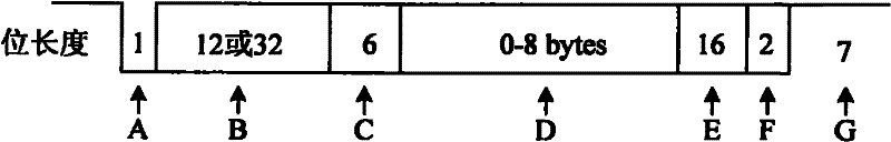
[0047] First of all, the CAN bus protocol supports four communication frames: data frame, remote frame, error frame, and overload frame. Wherein the data frame realizes the data transfer from the sending node to the receiving node. In this embodiment, the application layer message sent and received by the CAN node during the application layer communication can be carried by the CAN data frame. In actual application, it is not excluded Carried by other frames. The format of the dataframe is as figure 1 shown.

[0048] Each subfield of the CAN bus data frame is:

[0049] A: fra...

Embodiment 2

[0210] Embodiment two, a kind of CAN bus system, comprises CAN bus, several CAN nodes;

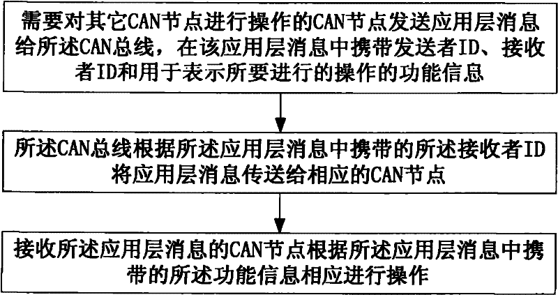
[0211] The CAN node is used to send an application layer message to the CAN bus when other CAN nodes need to be operated, and the application layer message carries the sender's identification, the receiver's identification and the information used to indicate the operation to be performed. Function information, using the identity of the node as the sender identity, using the identity of the CAN node as the operation object as the receiver identity; and after receiving the application layer message, according to the function information carried in the application layer message carry out corresponding operations;

[0212] The CAN bus is used to transmit the application layer message to the corresponding CAN node according to the receiver identifier carried in the application layer message.

[0213] In this embodiment, the CAN node is also used to carry the communication mode information of ...


PUM


Abstract

The invention discloses a controller area network (CAN) bus system and an application layer communication method in the CAN bus system. The method comprises the following steps: a CAN node needing to operate other CAN nodes sends an application layer message to the CAN bus, the application layer message carries a sender mark, a receiver mark and function information for expressing the operation to be carried out; a mark of the node is used as the sender mark, and a mark of the CAN node used as an operation object is used as the receiver mark; the CAN bus transmits the application layer message to the corresponding CAN node according to the receiver mark carried in the application layer message; and the CAN node receiving the application layer message carries out corresponding operation according to the function information carried in the application layer message. The invention is simple and practical, is convenient for generalization and transplantation and can be suitable for a plurality of industrial automation technical equipment using the CAN bus.

Description

technical field [0001] The invention relates to a CAN (Controller Area Network, controller area network) bus, in particular to a CAN bus system and an application layer communication method therein. Background technique [0002] The CAN bus was originally a serial data communication bus developed by the German Bosch company in order to solve the data exchange between many controllers and measuring equipment in the car (see Bosch. CANSpecification, version 2.0, 1991, 9), and later developed It is the international standard ISO11898. The biggest feature of the CAN bus is that the data link layer adopts mechanisms such as message priority arbitration, automatic response, CRC (Cyclical Redundancy Check, cyclic redundancy check) automatic verification, and error retransmission. Because the CAN bus has high reliability, fast transmission rate, long communication distance, easy use, maintenance and network expansion, it has been widely used in various industrial field control fiel...

Claims


Application Information

Patent Timeline
Patent Type & Authority Patents(China)
IPC IPC(8): H04L12/40H04L29/08
Inventor 韩利何震球姚宏
Owner 北京和利时电机技术有限公司
Why Eureka
Try Eureka