Drive device for hybrid vehicle

A hybrid vehicle and driving device technology, applied in hybrid vehicles, power devices, electric power devices, etc., can solve the problems of increased pump loss and reduced performance of oil pumps, and achieve the effect of shortening the length of the axis and realizing miniaturization

Inactive Publication Date: 2010-01-13
AISIN AW CO LTD +1
View PDF1 Cites 45 Cited by
  • Summary
  • Abstract
  • Description
  • Claims
  • Application Information

AI Technical Summary

Problems solved by technology

In addition, due to the increase in the size of the oil pump, there are also problems such as increased pump loss due to an increase in the amount of oil in the pump, and reduced performance of the oil pump.

Method used


Image

  • Drive device for hybrid vehicle
  • Drive device for hybrid vehicle
  • Drive device for hybrid vehicle

Examples


no. 1 approach

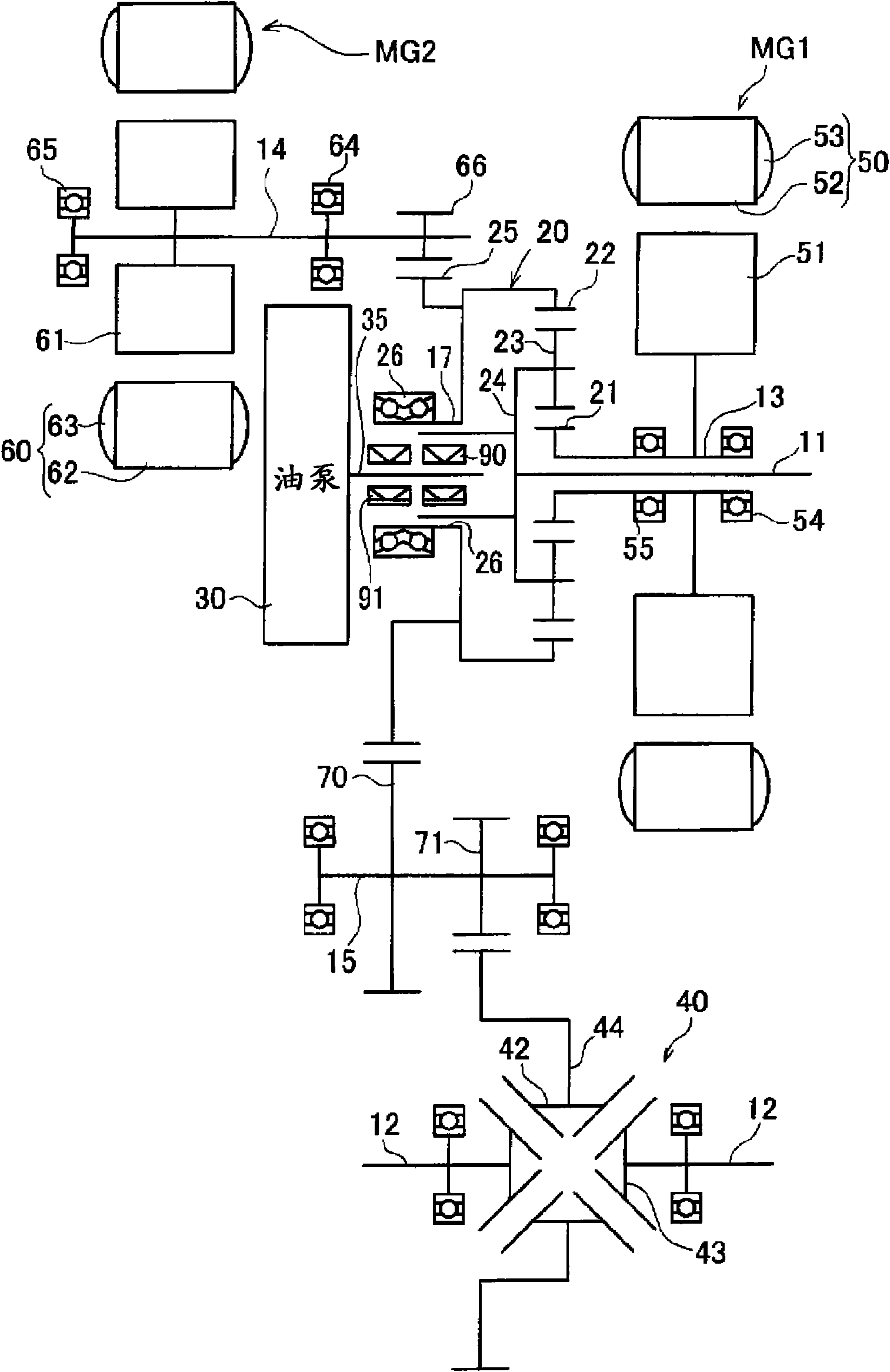
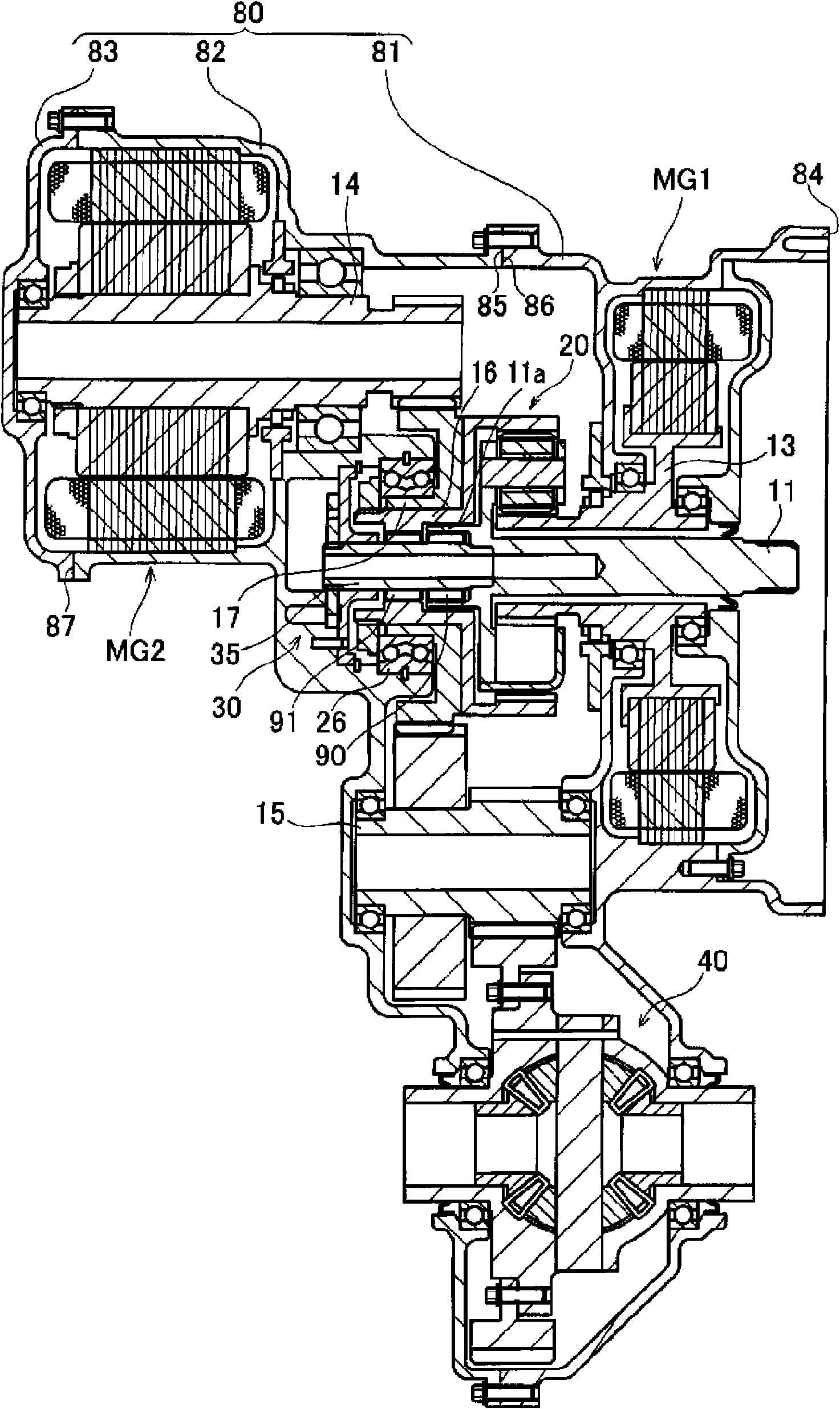
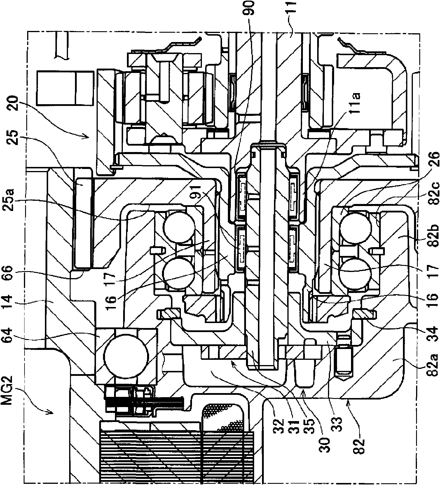
[0029] The drive device according to the first embodiment is a drive device in which a motor is disposed on a shaft different from the input shaft. refer to Figure 1 to Figure 4 The driving device of the first embodiment will be described. figure 1 It is a schematic diagram of the driving device of the first embodiment. figure 2 It is a cross-sectional view showing a schematic configuration of the driving device according to the first embodiment. image 3 It is an enlarged sectional view near the oil pump. Figure 4 It is a layout diagram showing the layout relationship of components included in the drive device according to the first embodiment.

[0030] The driving device of the first embodiment, such as figure 1 As shown, it includes an input shaft 11 for inputting power from an engine (not shown), a motor generator MG1, a motor generator MG2, and a differential gear device connected to the motor generator MG1, the motor generator MG2, and the input shaft 11. 20 . An...

no. 2 approach

[0071] Next, a second embodiment will be described. In the drive device of the second embodiment, the arrangement positions of the motor generator MG2 and the oil pump 30 are different from those of the first embodiment. Therefore, in the following description, differences from the first embodiment will be mainly described, and the same points will be given the same reference numerals in the drawings, and their description will be appropriately omitted.

[0072] refer to Figure 5 A drive device according to a second embodiment will be described. Figure 5 It is a cross-sectional view showing a schematic configuration of a driving device according to a second embodiment. Such as Figure 5 As shown, in the drive device according to the second embodiment, motor generator MG2 and counter gear 25 are arranged adjacent to each other coaxially with input shaft 11 . A rotor shaft 14 of motor generator MG2 is connected to a counter gear shaft 16 . Therefore, unlike the first embo...


PUM


Abstract

A drive device for a hybrid vehicle, in which a oil pump can be operated by power of either an input side rotating shaft or an output side rotating shaft without a reduction in performance of the oil pump and which is downsized by reducing the axial length of the drive device. An oil pump shaft (35) connected to an oil pump gear mechanism (31) of the oil pump (30) is drivably connected to an input shaft (11) through a one way clutch (90). The oil pump shaft (35) is also drivably connected to a ring gear shaft (16) connected to a counter gear (25) through a one way clutch (91). The one way clutches (90, 91) are caused to axially overlap a bearing (26) for supporting the counter gear (25), and this arranges the one way clutches (90, 91) at positions on the inner peripheral side of a boss (17) of the counter gear (25).

Description

technical field [0001] The present invention relates to a drive device mounted on a hybrid vehicle using an engine and an electric motor as drive sources. Background technique [0002] In the driving device of a hybrid vehicle using an engine (internal combustion engine) and an electric motor as a driving source, it is necessary to transmit (output) the power of the two systems to the drive shaft connected to the drive wheels through the differential device as its power train Structures Various structures are proposed. Such a drive device includes an oil pump that generates oil pressure for lubricating the components of the drive device. In addition, in a hybrid vehicle, it is necessary to run using the power output from the electric motor, and to operate the oil pump even when the engine is stopped. [0003] Therefore, a driving device having an oil pump that can be driven by either an input shaft that inputs power from a power source or an output shaft that outputs power...

Claims


Application Information

Patent Timeline
Patent Type & Authority Applications(China)
IPC IPC(8): B60K6/40B60K6/26B60K6/365B60K6/383B60K6/445H02K7/116H02K7/14
CPCY02T10/6239F16H57/0486B60K25/02B60K1/02B60K6/383H02K7/006B60K6/445B60K6/547F16H57/0441B60K6/365B60K5/04Y02T10/62
Inventor 三治广明佐田夏木新智夫土田充孝驹田英明
Owner AISIN AW CO LTD
Why Eureka
Try Eureka