Biological waste treatment plant

A technology of biological treatment and treatment tank, applied in the direction of bio-organic part treatment, chemical/physical process, educts, etc., can solve the problems of screw propeller elevation, correction, difficult temperature control, etc., and achieve the effect of reducing air volume

Active Publication Date: 2010-01-13
SCT SORAIN CECCHINI TECNO
View PDF1 Cites 3 Cited by
  • Summary
  • Abstract
  • Description
  • Claims
  • Application Information

AI Technical Summary

Problems solved by technology

[0009] Apart from the non-uniform advancement of the matter (a defect corrected by extraction and re-submersion of the screw propellers running along their axis), the other defects of the Swedish patent are not corrected, on the contrary, it necessarily adds another disadvantage: The building must be large enough to accommodate the entire station, which is fairly tall to be able to raise the auger
[0012] This station has two main disadvantages: there is only one trolley on which the screw pusher is moun

Method used


Image

  • Biological waste treatment plant
  • Biological waste treatment plant
  • Biological waste treatment plant

Examples


Embodiment Construction

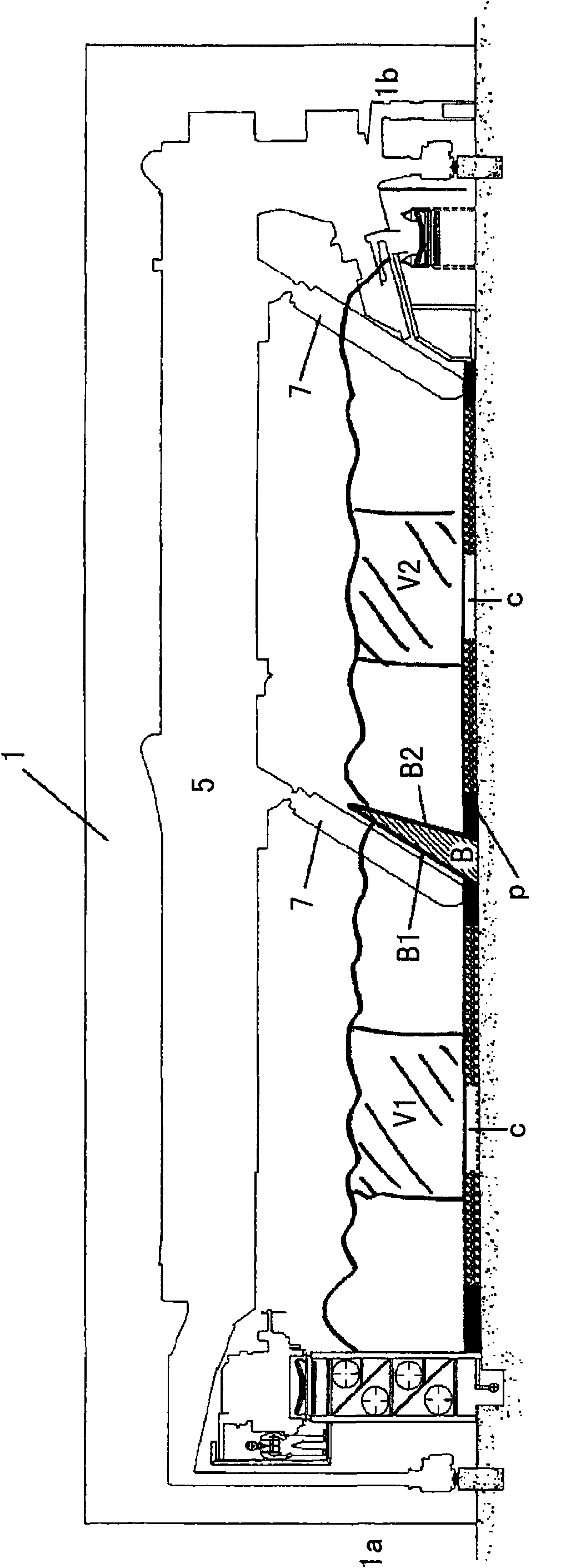
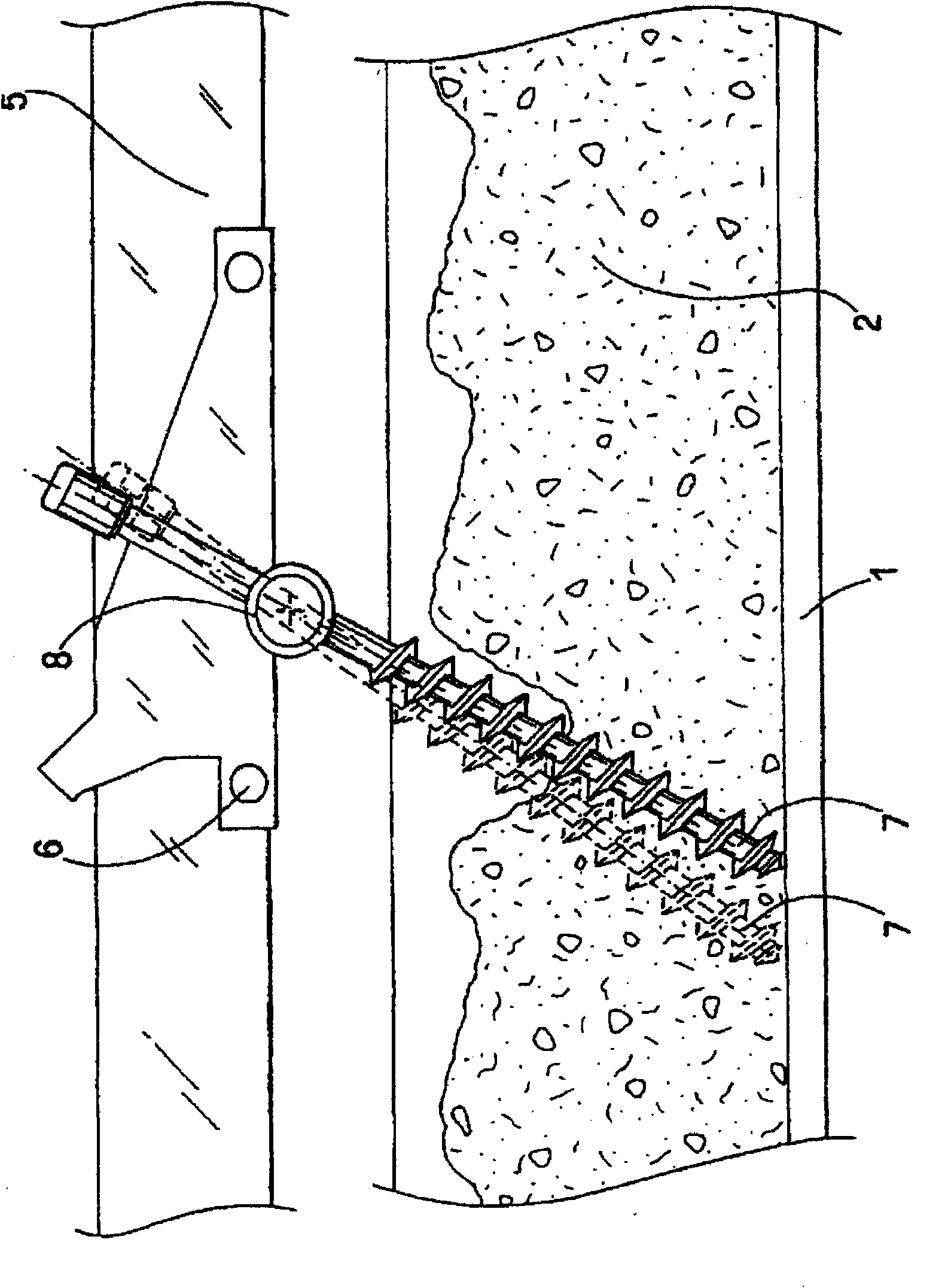
[0038] Reference is now made to the accompanying drawings and in particular to the figure 1 , organic matter 2( figure 1 (not shown in ) is fed into the treatment tank 1 by means of a conveyor belt or the like, preferably in a continuous manner. Above the treatment tank 1 is a bridge 5 along which two or more trolley wheels run, on which a set of one or more screw pushers 7 are mounted, characterized in that: (i) they wind around themselves axis of rotation, and are carried by the bridge 5 to move from the end of the treatment tank 1 to the opposite end; (ii) they move along the bridge 5 across the treatment tank 1 from one end to the opposite end; (iii) they can pass around their Axis of rotation 8 ( figure 1 (not shown in ) are turned over so that they can be drawn out of the organic matter when required.

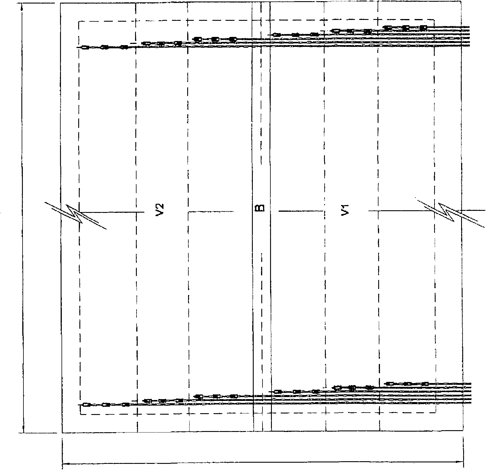
[0039] image 3 A preferred embodiment of the working position of the screw propellers 7 is shown, which, although they all sweep the bottom of the treatment tank, ha...


PUM


Abstract

The present invention refers to a biological waste treatment plant. The treatment tank 1 is divided in at least two treatment basins V1, V2 whereby each basin is separated from the other by means of a barrier B. The barrier B has two walls (B1 and B2) the one facing the inflowing side, the other one facing the outflow side and each basin is provided with at least one mechanical stirring tool. Each basin is provided with an aeration system divided into zones.

Description

technical field [0001] The invention relates to a biological waste treatment station. Background technique [0002] Every day, huge amounts of organic waste are generated through the human food chain, in agriculture and through the agricultural and industrial sectors. This organic waste constitutes a large proportion of solid municipal waste, is a major component of sewage and constitutes the residues of industry, agriculture and other industries. [0003] The question is what to do with this waste in order to prevent it from entering the sewer and to reuse it. [0004] Aerobic decomposition (composting) by microorganisms is undoubtedly a very efficient and economical technology. Currently known biological treatment stations generally work by feeding organic matter continuously or in batches into treatment tanks of various shapes, in which the organic matter is stirred by mechanical means in order to obtain a homogenized state, and to In order to form a space for the infl...

Claims


Application Information

Patent Timeline
IPC IPC(8): C05F17/02F26B21/00C05F17/00B01F7/16
CPCB01F7/00416B01F7/021B01F13/0038B01F7/1655F26B17/22C05F17/0235F26B25/04F26B9/10B01F7/08B01F13/0035Y02P20/145Y02P20/129C05F17/939Y02W30/40B01F27/1143B01F27/61B01F27/72B01F27/83B01F33/5022B01F33/502
Inventor 阿尔贝托·卡雷拉
Owner SCT SORAIN CECCHINI TECNO
Why Eureka
Try Eureka