Tangential telescopic ultrasonic torsional transducer

An ultrasonic and transducer technology, applied in the field of tangentially telescopic ultrasonic torsional vibration transducers, can solve the problems of low power and amplitude, complex structure, small power and output amplitude of torsional transducers, etc. And the effect of easy bonding, simple driving method and less energy loss

Inactive Publication Date: 2010-01-20
BEIHANG UNIV
View PDF0 Cites 7 Cited by
  • Summary
  • Abstract
  • Description
  • Claims
  • Application Information

AI Technical Summary

Problems solved by technology

Theoretically, it is possible to make torsional transducers through tangentially polarized piezoelectric ceramics, but it is difficult to realize tangentially polarized piezoelectric ceramics in the manufacturing process.
Using piezoelectric ceramics polarized in the longitudinal direction can also achieve torsional vibration according to a certain bonding method, but the power and output amplitude of the torsional transducer manufactured by this method are small
The longitudinal ultrasonic vibration can also be converted into torsional vibration through a special structure, but the structure is more complicated
The mode conversion method can also be used to convert the bending vibration mode into torsional vibration, but this form is more complicated in terms of excitation, requiring two waveforms to be accurately coupled. In addition, the power and amplitude of this torsional transducer are not very large, and the other modes of vibration

Method used


Image

  • Tangential telescopic ultrasonic torsional transducer
  • Tangential telescopic ultrasonic torsional transducer
  • Tangential telescopic ultrasonic torsional transducer

Examples


Embodiment Construction

[0043] The present invention will be further described in detail below in conjunction with the accompanying drawings.

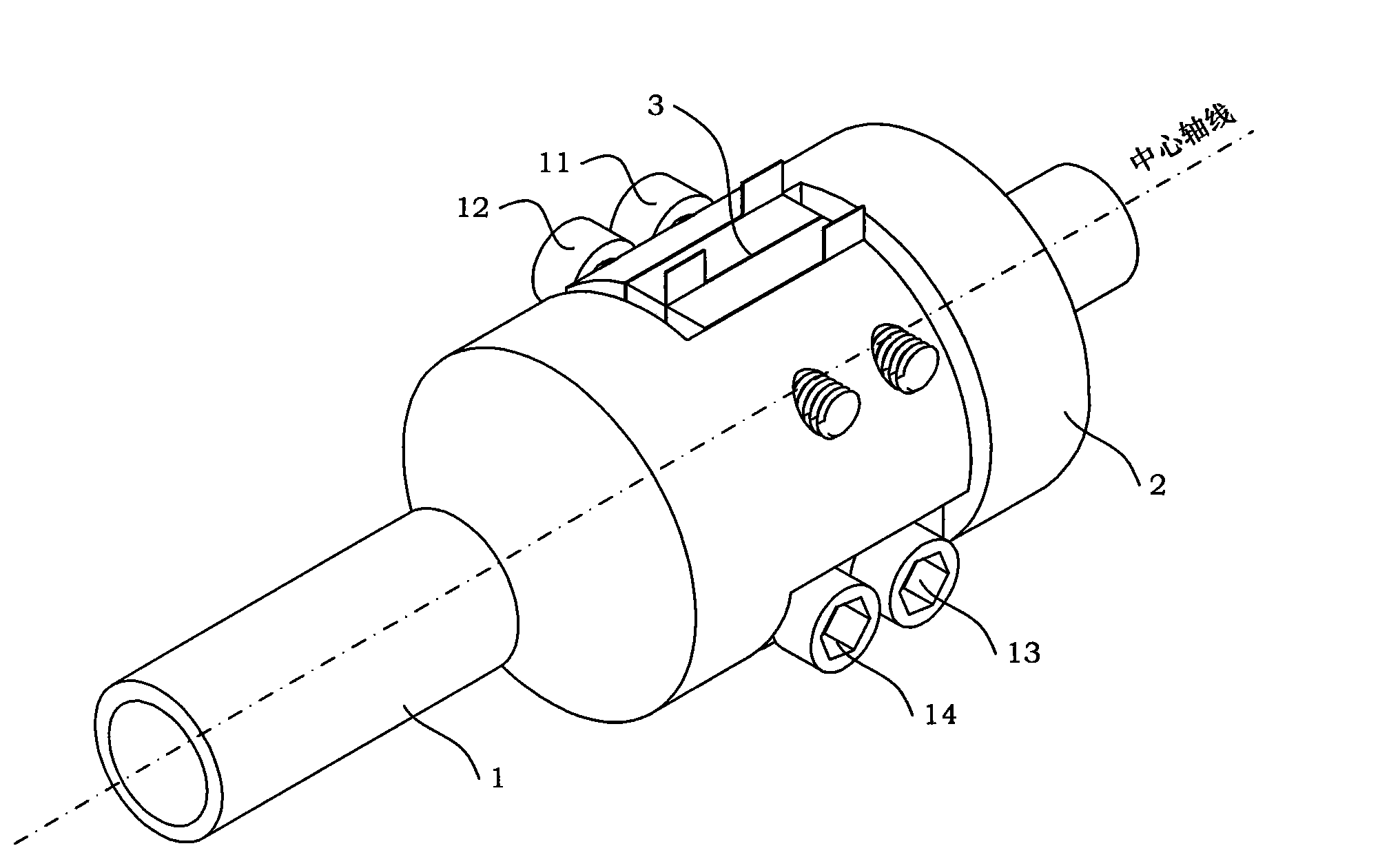
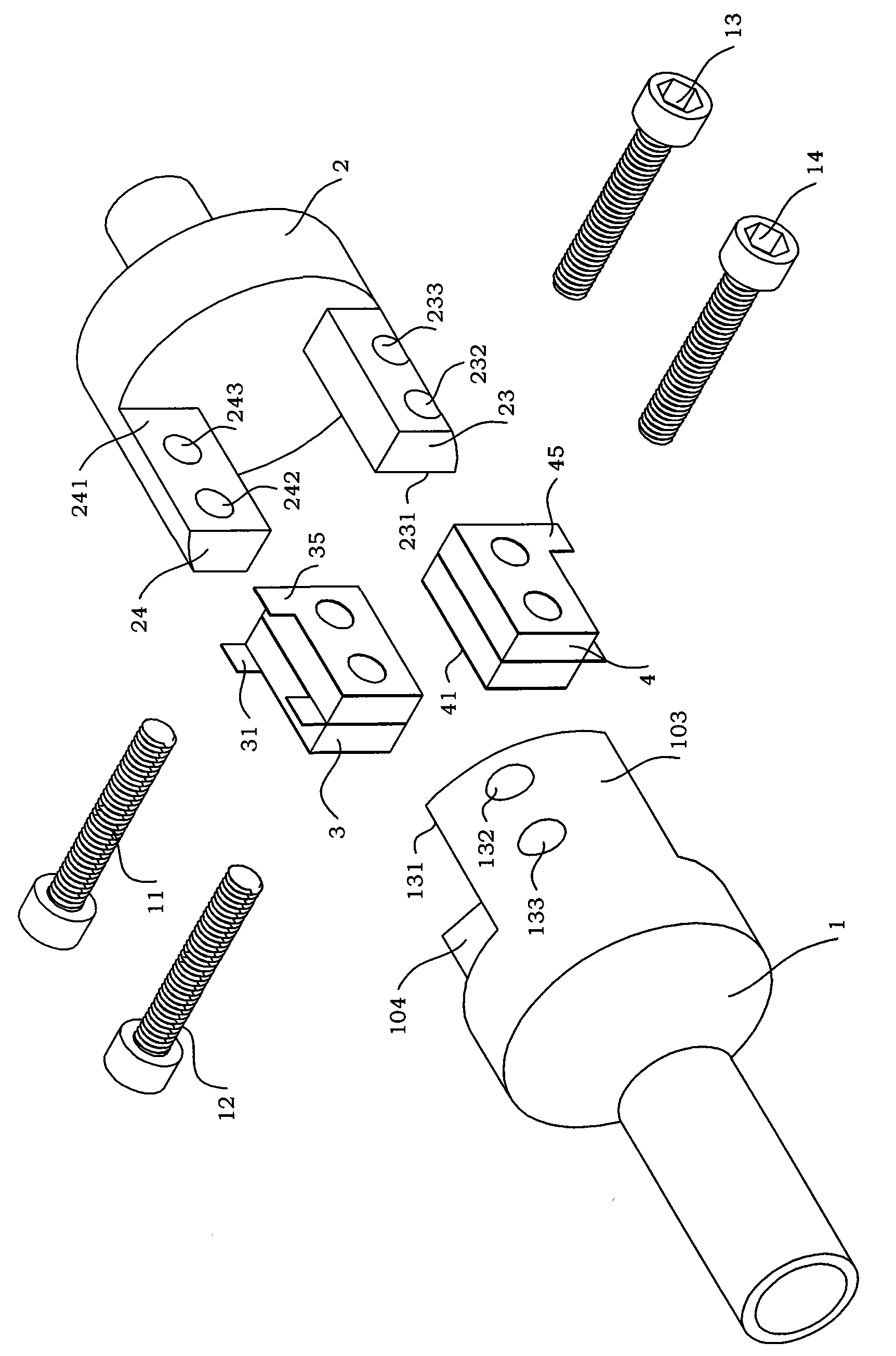
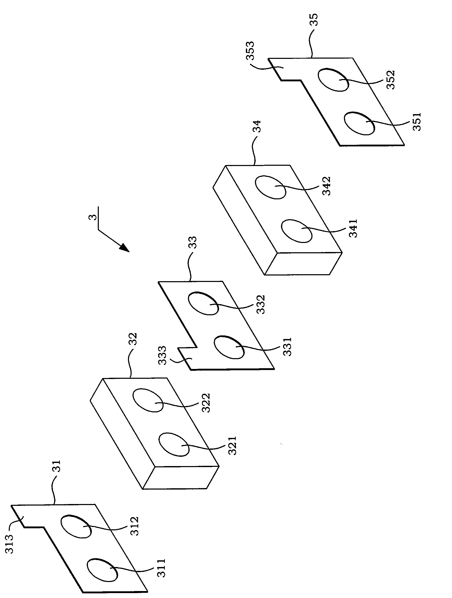
[0044] A tangential telescopic ultrasonic torsional transducer of the present invention includes a front cover body 1, a rear cover body 2, an A drive assembly 3, a B drive assembly 4 and four long screws (A long screw 11, B long screw 12, C long screw 13, D long screw 14), the structure of A driving assembly 3 and B driving assembly 4 is identical.

[0045] 1. Front cover 1

[0046] see Figure 4 , Figure 4A , Figure 4B As shown, the front cover 1 is integrally formed and processed. The front cover 1 is divided into a horn 101 , a cylindrical seat 102 , an A connecting arm 103 and a B connecting arm 104 according to the functions realized.

[0047] The contact surface 131 of the A connecting arm 103 is provided with an A threaded hole 132 and a B threaded hole 133 , and the A threaded hole 132 and the B threaded hole 133 penetrate the contact surface 1...


PUM


Abstract

The invention discloses a tangential telescopic ultrasonic torsional transducer which comprises a front cover body, a back cover body, an A driving component, a B driving component and four long screws, wherein, the structures of the A driving component and the B driving component are the same. The two driving components of the tangential telescopic ultrasonic torsional transducer are symmetrically distributed along a central axis line of the transducer, the two driving components generate a pair of stretching vibrations with the same frequency, amplitude and vibration direction in the tangential direction of the transducer, the vibrations lead two connecting arms on the front cover body to generate a pair of tangential vibrations with the same frequency, amplitude and vibration direction, the vibrations directly lead the front cover body to generate pure torsional vibration in the tangential direction, and large-amplitude torsional vibration is output after amplification by an amplitude varying pole, thereby obtaining the ultrasonic pure torsional vibration by the simple way of tangential direct driving.

Description

technical field [0001] The present invention relates to a transducer, more particularly, refers to a tangential telescopic ultrasonic torsional vibration transducer, suitable for ultrasonic vibration cutting (vibration drilling, vibration reaming and vibration tapping), ultrasonic welding , Ultrasonic motors and ultrasonic fatigue experiments and other fields. Background technique [0002] In the field of vibration cutting, especially in the processing of difficult-to-machine materials and micro-hole processing, torsional vibration has obvious advantages. Ultrasonic torsional vibration drilling can significantly reduce drilling force, improve drilling quality, and reduce exit burrs; ultrasonic torsional vibration reaming can suppress built-up edge generated in low-speed machining and improve hole surface quality; ultrasonic torsional vibration tapping can greatly Reduce tapping torque, improve tapping efficiency, improve tool life and thread quality. [0003] In the field ...

Claims


Application Information

Patent Timeline
Patent Type & Authority Applications(China)
IPC IPC(8): B06B1/06
Inventor 张德远卢慧敏姜兴刚秦威张文全
Owner BEIHANG UNIV
Why Eureka
Try Eureka