System and method for metering cooling/heating amount of air conditioners

A heat metering and air conditioning technology, which is applied to the cooling/heat metering system and cooling/heat metering field of fan coil air conditioners, can solve the problems of complicated installation, unfavorable energy saving, large maintenance, etc., to reduce hardware investment, The effect of enriching software design and reducing failure rate

Active Publication Date: 2010-01-20
纪周
View PDF0 Cites 14 Cited by
  • Summary
  • Abstract
  • Description
  • Claims
  • Application Information

AI Technical Summary

Problems solved by technology

There is no theoretical basis for the above three methods of billing. They are all billing methods for big pot meals, which is not conducive to saving energy. It has not realized the "how much heat you use, how much you pay" required by the Ministry of Construction
[0004] Some also use a cold / heat dual-purpose heat meter installed on the waterway of the fan coil unit of the air conditioner for cold / heat measurement. Although this measurement method can directly measure the amount of energy used, it has the following disadvantages: (1) 1. It is necessary to destroy the original water supply pipes when installing existing buildings, and the installation is complicated; (2), the cost is high, the one-time investment is large, and the life of the heat meter is only five years. Periodic calibration is required during use, and the maintenance volume is relatively large ; (3), because the air conditioner operates under a small temperature difference between the inlet and the return water, and the measurement accuracy of the heat meter is very low under the small temperature difference; (4), due to the water quality problem, the household heat meter is easy to block during use

Method used


Image

  • System and method for metering cooling/heating amount of air conditioners
  • System and method for metering cooling/heating amount of air conditioners
  • System and method for metering cooling/heating amount of air conditioners

Examples


Embodiment Construction

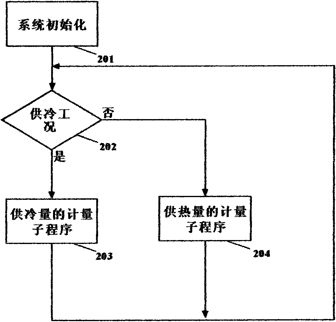
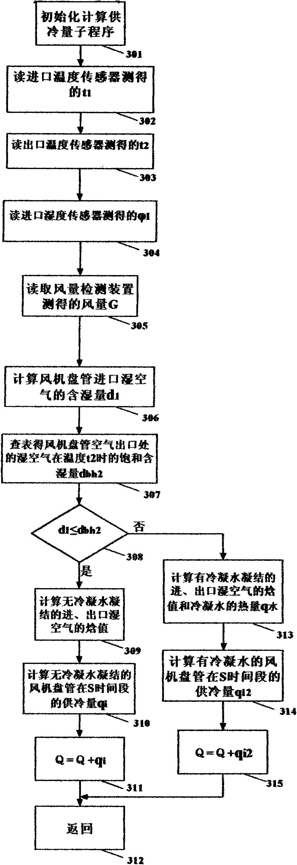
[0051] Below in conjunction with accompanying drawing and embodiment the present invention is further described:

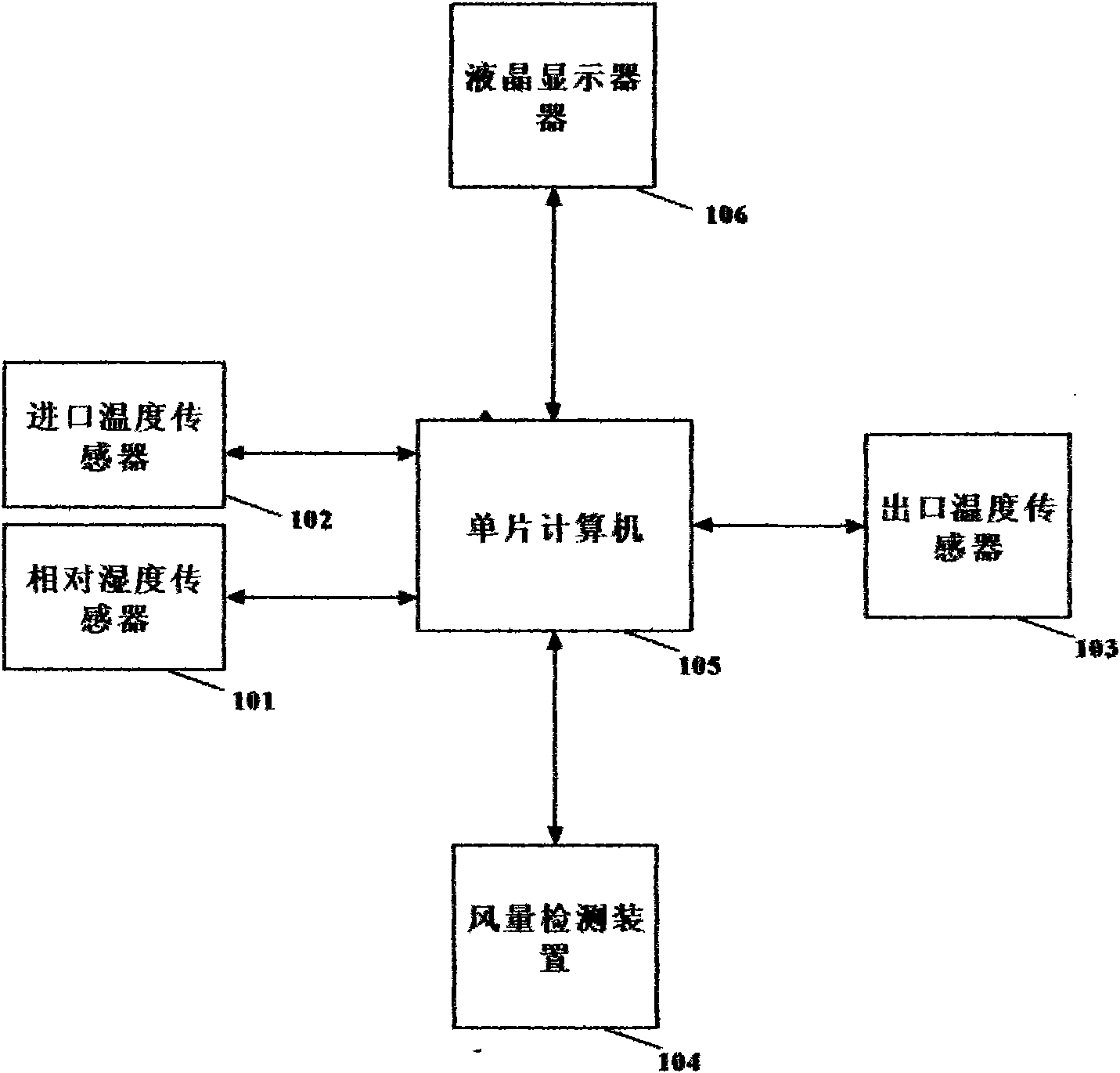
[0052] See figure 1 , figure 1 It is a hardware block diagram of the fan coil air conditioner cooling / heat metering system of the present invention.

[0053] In this embodiment, both the inlet temperature sensor 102 and the outlet temperature sensor 103 of the fan coil unit are digital temperature sensors, and the relative humidity sensor 101 is a digital humidity sensor. The humidity sensor 101 and the temperature sensor 102 are placed at the air inlet of the fan coil unit, and the temperature sensor 103 is placed at the air outlet of the fan coil unit. The single-chip computer 105 adopts a 16-bit low-power single-chip microcomputer, and the liquid crystal display 106 displays cooling capacity, heat supply, inlet and outlet temperatures and working hours. The temperature sensor 102 , the temperature sensor 103 , the relative humidity sensor 101 , the air volum...


PUM


Abstract

The invention discloses a system and a method for metering cooling/heating amount of fan-coil air conditioners. The system comprises a single chip microcomputer, an inlet/outlet temperature sensor, an inlet relative humidity sensor and an air-volume detection device which are connected with I/O ports of the single chip microcomputer. The method for metering cooling amount comprises: 1) reading the air temperature of an inlet and an outlet, the relative humidity of the inlet and air volume; 2) calculating the moisture content of inlet air; 3) judging whether condensed water exists, changing over to 4) if not or changing over to 7) if so; 4) calculating the enthalpy value of inlet/outlet air with no condensed water; 5) calculating the cooling amount of an S period with no condensed water; 6) accumulating cooling amount; 7) calculating the enthalpy value of the inlet/outlet air with condensed water and the heat of the condensed water; 8) calculating the cooling amount of the S period with condensed water; and 9) accumulating cooling amount. The method for metering heating amount comprises: 1) reading the air temperature of the inlet and the outlet, the relative humidity of the inlet and the air volume; 2) calculating the moisture content of inlet air; 3) calculating the enthalpy value of the inlet/outlet air; 4) calculating the heating amount of the S period; and 5) accumulating heating amount.

Description

Technical field [0001] The present invention relates to a fan coil air conditioner cooling / heat metering system and cooling / heat metering method, in particular to a fan coil air conditioner cooling system using two temperature sensors and only one relative humidity sensor and air volume detection device The invention relates to a heat metering system and a metering method for calculating the cooling / heat supply of a fan coil air conditioner by using the enthalpy difference method, belonging to the technical field of heat energy metering. Background technique [0002] Previously, the following methods were generally used for cooling / heating metering of fan coil air-conditioning pipes: [0003] (1), according to the area of ​​the user's cooling / heating room; (2), according to the time of cooling / heating; (3), according to the temperature of the room. There is no theoretical basis for the above three methods of billing, and they are all billing methods for big pot meals, which...

Claims


Application Information

Patent Timeline
Patent Type & Authority Applications(China)
IPC IPC(8): G01K17/08
Inventor 纪周纪睿纪义盛
Owner 纪周
Why Eureka
Try Eureka