
Method for imaging anisotropic medium through utilization of vertical seismic profile data

A technology of vertical seismic section and anisotropy, which is applied in the field of geophysical exploration, and can solve problems such as large changes in ray propagation direction, lower resolution, and obvious anisotropy characteristics of VSP data

Active Publication Date: 2010-01-20
BC P INC CHINA NAT PETROLEUM CORP +1
View PDF0 Cites 37 Cited by
  • Summary
  • Abstract
  • Description
  • Claims
  • Application Information

AI Technical Summary

Problems solved by technology

However, for Walkaway VSP (the VSP observation method in which the downhole receiving instrument is fixed in a certain depth range of the receiving well, and the source moves away from (asymptotically) the wellhead at a certain interval) and three-dimensional VSP observation, the excitation points with different well-source distances The propagation direction of the ray changes greatly, and the collected VSP data has obvious anisotropy characteristics; and the Walkaway VSP and 3D VSP data imaging requires multi-shot data stacking, and the anisotropy strength of the data collected at different excitation points is different. Therefore, using the traditional imaging method based on the isotropic medium model to image the Walkaway VSP and 3D VSP data will bring some problems to the imaging results: one is that the anisotropy brings a large error to the imaging position; the other is that The resolution reduction and obvious "seams" caused by the superposition of different phases of different shots with different degrees of anisotropy

Method used


Image

  • Method for imaging anisotropic medium through utilization of vertical seismic profile data
  • Method for imaging anisotropic medium through utilization of vertical seismic profile data
  • Method for imaging anisotropic medium through utilization of vertical seismic profile data

Examples


Embodiment Construction

[0045] The present invention will be described in detail below in conjunction with the accompanying drawings.

[0046] The specific embodiment of the present invention is:

[0047] 1) Forward simulation of Walkaway VSP and 3D VSP synthetic seismic records, and acquisition of actual Walkaway VSP seismic records.

[0048] 2) Separating the synthetic and actual VSP seismic records into wavefields, the separated wavefields include upward reflected longitudinal waves and upward converted waves.

[0049] 3) Calculate the velocity of the VSP layer by using the first arrival time of the VSP with zero well-source spacing, and establish the initial velocity-depth model for the actual VSP data migration, and then use the multiple first-arrival time-depth time-distance curves of the Walkaway VSP or 3D VSP to inverse Interval velocities and anisotropy coefficients for VTI (Vertical Axis Anisotropy) models.

[0050] 4) Load the initial velocity model. The initial velocity model includes ...


PUM


Abstract

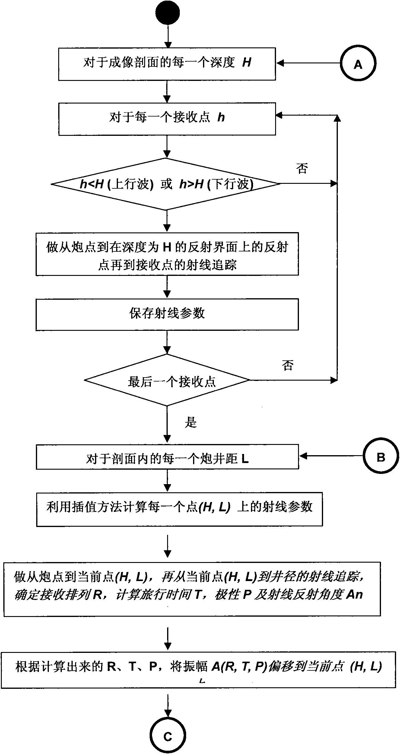
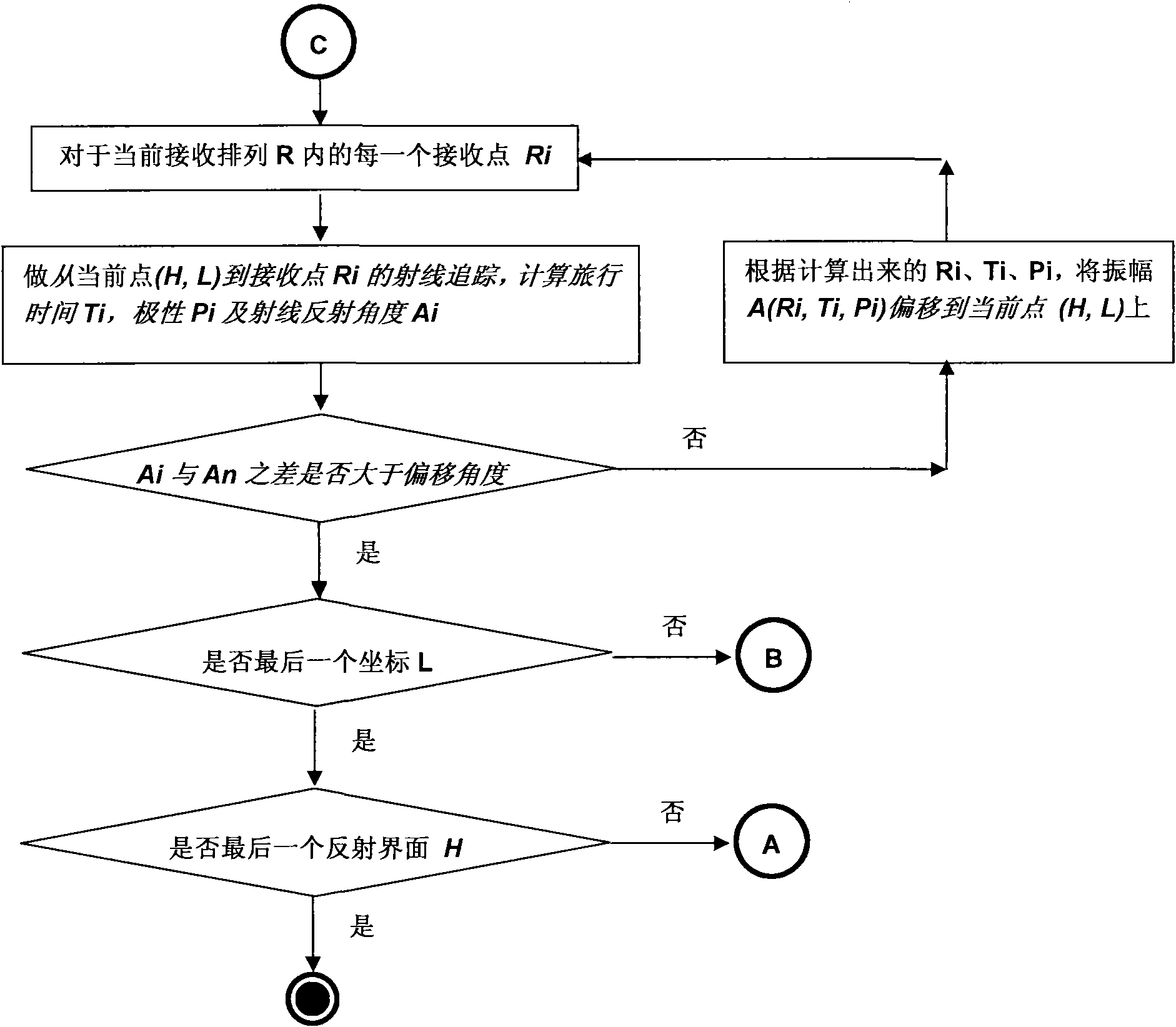
The invention relates to a method for imaging an anisotropic medium through utilization of vertical seismic profile data. The method comprises the following steps: firstly, establishing an initial depth-speed model; secondly, establishing an initial speed model through utilization of an interval velocity and an anisotropic coefficient of a Walkaway VSP or three-dimensional VSP first-arrival time inversion model; converting a plane of random normal direction of a three-dimensional space into a plane with normal parallel to the Z axis; loading information of an observation system; determining a reflecting layer of which rays run through from a shooting point to a receiving point; seeking an approximate ray parameter; determining a coordinate of the reflecting point in a reflecting interface and recording the corresponding sequence number of the receiving point; determining the traveling time from the reflecting point to the receiving point and an emergence angle of the ray in the reflecting point; and outputting imaging gather data. The method simplifies calculation, has high operation efficiency, improves the precision and the resolution of the VSP imaging result and can conveniently carry out migration imaging on Walkaway VSP or three-dimensional VSP vertical wave, transverse wave or converted wave data.

Description

technical field [0001] The invention relates to geophysical prospecting technology, and is a seismic data processing method, in particular a method for imaging anisotropic media by using vertical seismic section data. Background technique [0002] Migration imaging is an important step in the routine processing of vertical seismic profile (VSP) data. It is through the inversion calculation of the rearrangement of the collected VSP seismic data, so that the seismic wave energy can be returned to its real position in space, and the real underground structure can be obtained. image. Since the 1980s, various VSP imaging methods have been successively developed, for example, the VSP-CDP conversion method (Wyatt K.D. and Wyatt S.B., 1981; Cassell and Millahn, 1984; Dillon and Thomson, 1984, Genmeng Chen, 2000) ; F-K migration method using Born inversion (Clayton and Yedlin, 1980); Kirchhoff integration method ((Dillon, 1985; Wiggins and Levander, 1984, Keho, 1984); reverse time m...

Claims


Application Information

Patent Timeline
Patent Type & Authority Applications(China)
IPC IPC(8): G01V1/28
Inventor 张文波侯爱源耿伟峰王文闯吴恒
Owner BC P INC CHINA NAT PETROLEUM CORP
Learn More