
System for cascade cyclotron and dual-cooling storage ring

A cyclotron and storage ring technology, which is applied in the direction of magnetic resonance accelerators, accelerators, electrical components, etc., can solve the problems of complex processes, the inability to set up the experimental platform separately, and large footprint

Active Publication Date: 2010-01-20
INST OF MODERN PHYSICS CHINESE ACADEMY OF SCI
View PDF3 Cites 4 Cited by
  • Summary
  • Abstract
  • Description
  • Claims
  • Application Information

AI Technical Summary

Problems solved by technology

[0003] The disadvantage of the proton-heavy ion cooling storage ring disclosed in the prior art is that in the devices that use a cyclotron as the cooling storage ring injector, a cyclotron
Since the energy range to which the cyclotron can be accelerated is limited by magnets and high-frequency equipment, if there is a large difference between the ion energy provided by the ion source and the lowest ion energy that the cooling storage ring can accept, the cyclotron as an injector is required There is a wide energy range, which means that the process complexity and cost increase
However, in the device that uses a linear accelerator as a cooling storage ring injector, the linear accelerator can only provide pulsed proton-ion beams, and the cost is relatively high and the area occupied is relatively large.
At the same time, these accelerator devices all have a common defect. The cooling storage ring only adopts a single-ring structure, and the experimental platform cannot be set up separately, which makes the experiment interfered and restricted by the process of improving the beam quality.

Method used


Image

  • System for cascade cyclotron and dual-cooling storage ring
  • System for cascade cyclotron and dual-cooling storage ring
  • System for cascade cyclotron and dual-cooling storage ring

Examples


Embodiment Construction

[0016] Below in conjunction with the preferred embodiment shown in accompanying drawing, be described in further detail:

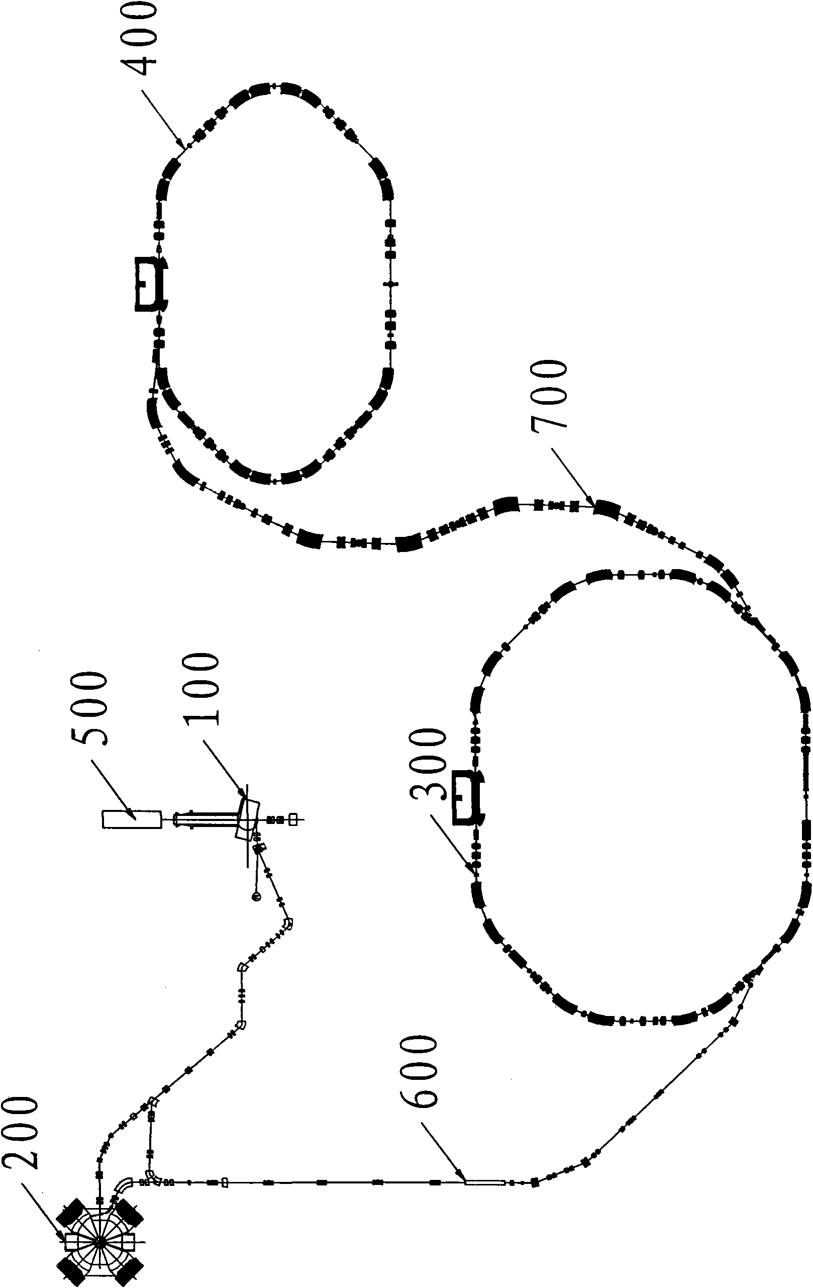
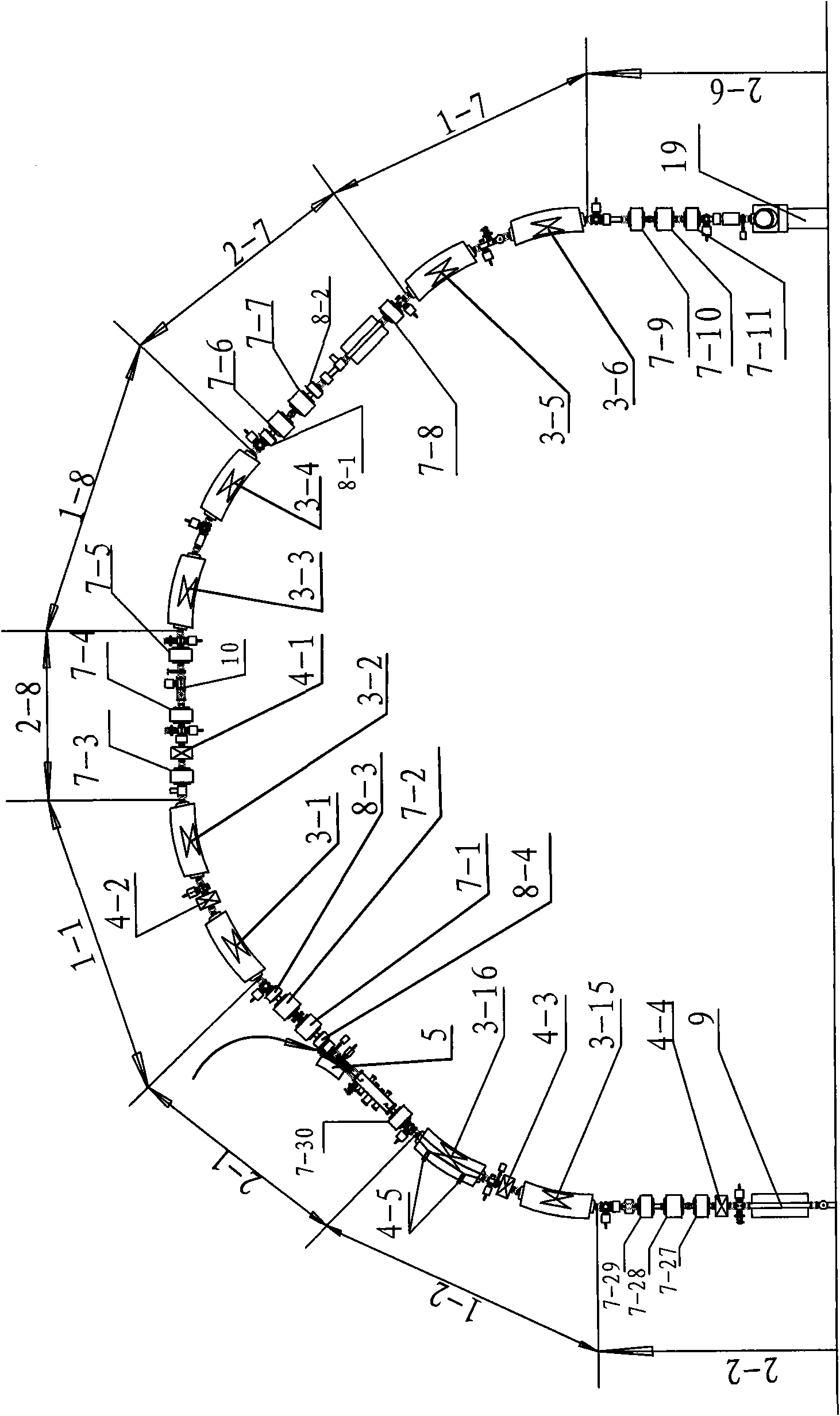
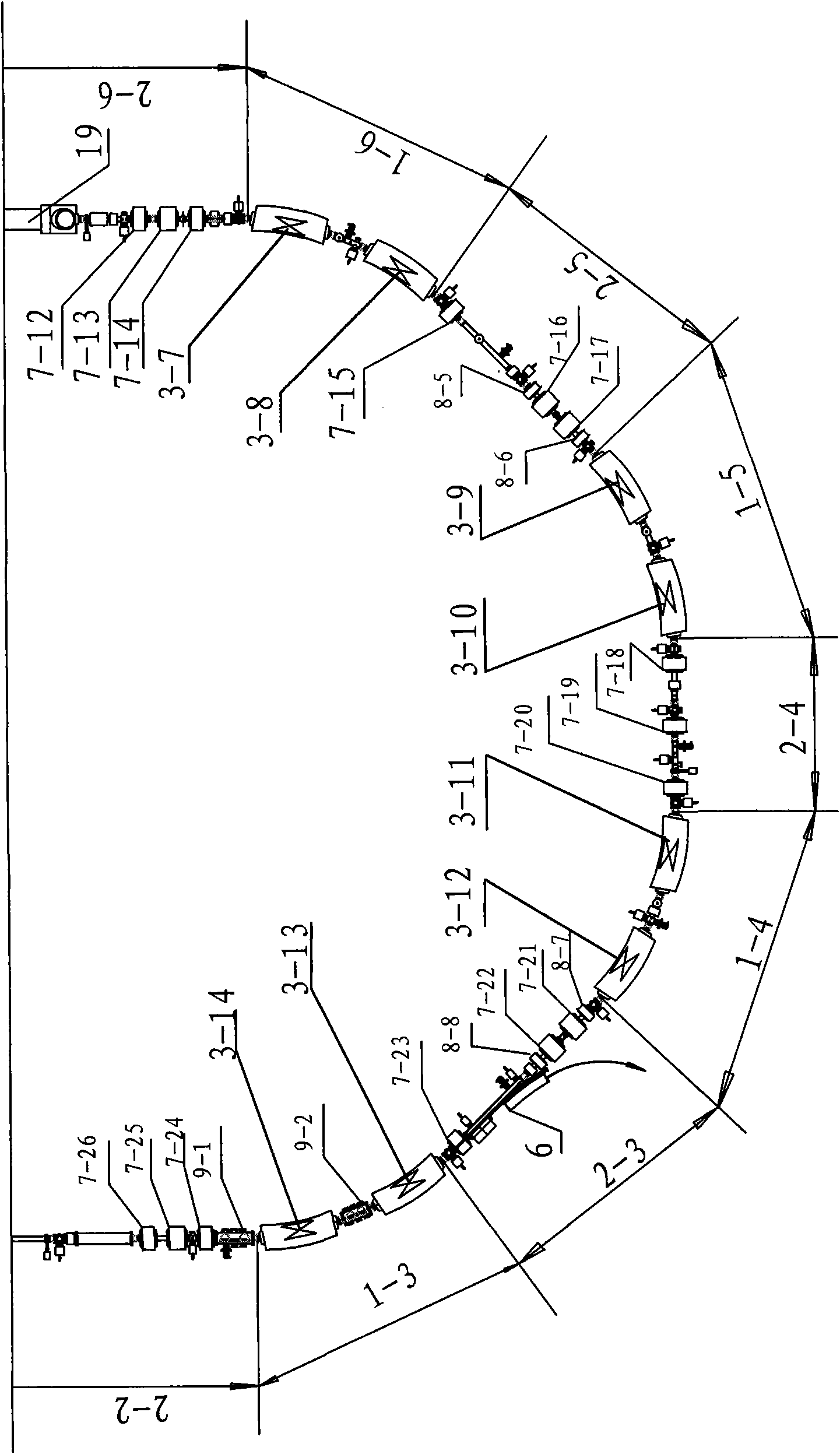
[0017] See figure 1 , 2 3. The cascaded cyclotron and dual cooling storage ring system includes an ion source 500 and a cooling storage ring 300 with a symmetrical magnetic focus structure, and is characterized in that the injection end of the cooling storage ring 300 with a symmetrical magnetic focus structure passes through the first An ion beam delivery line 600 is connected to the sector focus cyclotron 100 or / and the split sector focus cyclotron 200, and the outlet end of the cooling storage ring 300 of the symmetrical magnetic focus structure is connected to the asymmetric magnetic focus structure through the second ion beam delivery line 700 The cooling storage rings 400 are connected.

[0018]The cooling storage ring 300 of the symmetrical magnetic focusing structure includes an injection cutting magnet device 5, an extraction cutting magnet devi...


PUM


Abstract

The invention relates to a system for a cascade cyclotron and a dual-cooling storage ring, which comprises an ion source (500) and a cooling storage ring (300) with a symmetric magnetic focusing structure, wherein the injection end of the cooling storage ring (300) with the symmetric magnetic focusing structure is connected with a sector-focusing cyclotron (100) or / and a separated sector-focusing cyclotron (200) through a first ion beam transport line (600); and the leading-out end of the cooling storage ring (300) with the symmetric magnetic focusing structure is connected with a cooling storage ring (400) with an asymmetric magnetic focusing structure through a second ion beam transport line (700). The system uses the cascade combination of one or more cyclotrons and a synchrotron storage ring which is used for improving the quality of ion beam currents and is provided with an ion cooling technical device and simultaneously uses the cooling storage ring of the ion cooling technical device, meets high-precision nuclear physics experiments and atomic physics experiments effectively, and can be applied to application research projects such as material radiation, proton-heavy ion cancer treatment and the like.

Description

Technical field: [0001] The invention relates to the technical field of a construction method of a multipurpose proton-heavy ion research device, in particular to a cascaded cyclotron and double cooling storage ring system. Background technique: [0002] As a well-known proton-heavy ion accelerator, the cooling storage ring uses a magnetic field (to change the direction of movement of ions) and an electric field (to accelerate or decelerate ions) to synchronize the operation with the ions moving in the storage ring, so that the ions in the cooling storage ring energy change and storage. Cooled storage rings, as a kind of infrastructure for proton-heavy ion physics research, have been described in the prior art. [0003] The disadvantage of the proton-heavy ion cooling storage ring disclosed in the prior art is that in the devices that use a cyclotron as the cooling storage ring injector, one cyclotron is used. Since the energy range to which the cyclotron can be accelerate...

Claims


Application Information

Patent Timeline
IPC IPC(8): H05H13/00H05H13/10H05H7/00H05H7/04
Inventor 夏佳文原有进
Owner INST OF MODERN PHYSICS CHINESE ACADEMY OF SCI
Learn More