Jack-up platform

A self-elevating platform and pile leg technology, applied in water conservancy projects, artificial islands, underwater structures, etc., can solve the problems of not disclosing the effective method of controlling the driving mechanism, etc., and achieve the effect of increasing reliability

Active Publication Date: 2010-01-27
SIEMENS ENERGY AS
View PDF1 Cites 4 Cited by
  • Summary
  • Abstract
  • Description
  • Claims
  • Application Information

AI Technical Summary

Problems solved by technology

However, no effective method of controlling the drive mechanism has been disclosed so far

Method used


Image

  • Jack-up platform
  • Jack-up platform
  • Jack-up platform

Examples


Embodiment Construction

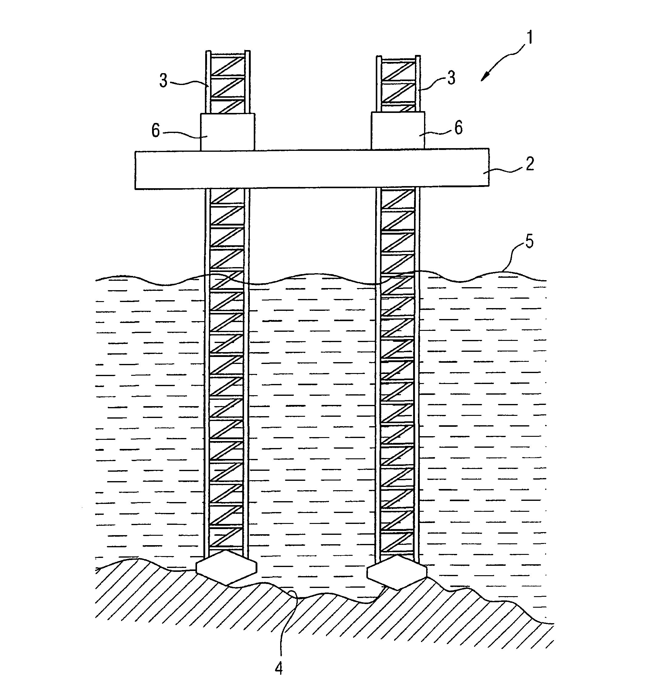
[0027] figure 1 An offshore jack-up platform 1 is schematically shown in the sea. It comprises a hull 2 ​​and some parallel, longitudinally movable legs 3 (ie 4, only two of which are shown). The hull 1 carries eg drilling equipment for oil field exploration. exist figure 1 In the state shown, all legs 3 are placed on an inclined seabed 4 as a fixed foundation. Hull 1 lifts 5 several meters above water level.

[0028] Each leg 3 is equipped with a driving mechanism 6 that contains a plurality of corresponding variable speed drives, i.e. 18 ( figure 1 not shown), the drive mechanism drives the rack-and-pinion device, and the drive mechanism is shared with all legs 3 closed-loop control unit ( figure 1 not shown) together. For example for triangular legs, the variable speed drives of each leg 3 are assigned to three separate groups, each group having its own drive A to F. They comprise permanent magnet motors (not shown) driving the legs 3 with infinitely variable speed. ...


PUM


Abstract

The invention relates to a jack-up platform (1) comprising a hull (2) and at least three longitudinally movable support legs (3) for said hull (1), at least one of said support legs (3) comprising at least one variable speed drive (8, 8A1to 8F2) as a part of a leg driving mechanism, wherein the platform (1) comprises a closed-loop control unit (7) for said driving mechanism, the closed-loop control unit (7) being connected with said variable speed drive (8, 8A1 to 8F2) via a bi-directional electronic bus (16) for transmitting control parameters (M*, M, N, R).

Description

technical field [0001] The invention relates to a self-elevating platform. A jack-up generally includes a hull and at least three longitudinally movable legs. The legs are all individually movable relative to the housing, ie can be raised or lowered using at least one drive mechanism. Usually, each leg has at least one independent driving mechanism. Background technique [0002] In order for the platform to be ready for work, the lower ends of the legs must rest on a solid foundation. To do this, lower these legs until they touch the foundation. The hull can then be raised to any position above the foundation by driving the legs accordingly to cause movement of the hull. The legs can be arranged in parallel or can be tilted to improve the stability of the jack-up platform. The foundation may have a sloped and / or uneven profile. In this case, the legs are driven to different positions to keep the hull balanced. [0003] For offshore jack-up platforms, generally, the hu...

Claims


Application Information

Patent Timeline
Patent Type & Authority Applications(China)
IPC IPC(8): E02B17/08
CPCE02B17/08
Inventor V·卡尔斯塔德
Owner SIEMENS ENERGY AS
Why Eureka
Try Eureka