Method and device for preparing metal powder

A metal powder and metal liquid technology, which is applied in the field of powder metallurgy, can solve the problems that the mass density of the spray mist cannot be kept uniform, the diameter of the spray droplets is large, and the complexity of the equipment increases. It is easy to implement, with few intermediate transition mechanisms, The effect of easy implementation

Active Publication Date: 2010-02-03
BAOSHAN IRON & STEEL CO LTD
View PDF0 Cites 20 Cited by
  • Summary
  • Abstract
  • Description
  • Claims
  • Application Information

AI Technical Summary

Problems solved by technology

[0005] Since the position where the metal liquid flow falls from the catheter to the centrifugal disk is difficult to align with the center of the disk, the mass density of the sprayed mist flow along the circumferential direction after the liquid flow is atomized from the high-speed rotating disk cannot be kept uniform, resulting in the spraying of droplets. Large differe

Method used


Image

  • Method and device for preparing metal powder

Examples


Embodiment 1

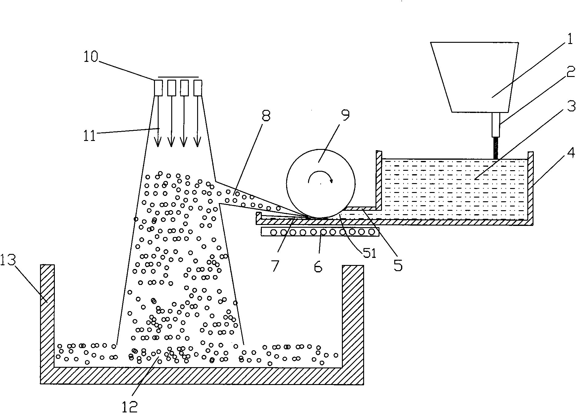
[0032] After heating the molten steel to 1650°C, tap the steel and pour it into the ladle. The flow rate of the molten steel is 1m / s. When it is filled to a height of 500mm, turn on the high-temperature drum, adjust the speed to 100rad / min, open the gas cooling nozzle, set the internal pressure to 0.8Mpa, and heat the bottom refractory material with the bottom heater to keep the temperature at 1350°C. After all the molten steel is sprayed, the powder is collected.

Embodiment 2

[0034] After heating the molten steel to 1630°C, tap the steel and pour it into the ladle. The flow rate of the molten steel is 1.2m / s. When the liquid is filled to a height of 600mm, turn on the high-temperature drum, adjust the speed to 120rad / min, open the gas cooling nozzle, set the internal pressure to 0.9Mpa, and heat the bottom refractory material with the bottom heater to keep the temperature at 1360°C. After all the molten steel is sprayed, the powder is collected.

Embodiment 3

[0036] After heating the molten steel to 1670°C, tap the steel and pour it into the ladle. The flow rate of the molten steel is 1.5m / s. When the liquid is filled to a height of 400mm, turn on the high-temperature drum, adjust the speed to 150rad / min, open the gas cooling nozzle, set the internal pressure to 1Mpa, and heat the bottom refractory material with the bottom heater to keep the temperature at 1300°C. After all the molten steel is sprayed, the powder is collected.

[0037] At present, most of the existing powder preparation processes are completed at the cost of consuming a large amount of inert gas, while the powder preparation process of the present invention uses mechanical energy to atomize molten steel, and the molten steel is pulverized by centrifugal force. During the atomization process, the flying direction is fixed, which facilitates the collection of powder, saves a lot of energy and gas resources, and reduces the cost; at the same time, the powder preparati...


PUM


Abstract

The invention relates to a method for preparing metal powder, which comprises the following steps that: a master alloy to be prepared is melted; the metal liquid is heated to a certain temperature, poured into a ladle, and injected into a pouring box through a water gap, the outlet end of the pouring box is provided with a film prefabricating guide groove for controlling the molten steel to a certain width, the far end on the top surface of the guide groove is provided with an opening and a high-temperature roller rotating at a high speed, the roller maintains a certain distance from the bottom of the film prefabricating guide groove, and the metal liquid is formed into a film by the roller and the film prefabricating guide groove; the roller rotates at a high speed, and throws away the molten metal attached on the surface when passing through the molten steel film so as to form molten drops; and a gas nozzle for jetting a cooling medium is arranged above the molten drops, and the molten drops are jetted and cooled by the cooling medium in the process of movement and are solidified at a very quick speed to form metal particles falling into a holding tank so as to form the metal powder.

Description

technical field [0001] The invention relates to powder metallurgy technology, in particular to a method and device for preparing metal powder. Background technique [0002] The method of atomizing metal liquid to form metal powder is one of the commonly used methods in powder metallurgy. For example, water atomization and gas atomization are two methods that use water or gas as a medium to impact metal liquid at high speed to prepare metal powder. In the case of water atomization, the particles are irregularly shaped and come in many different sizes; gas atomization generally forms spherical particles. The method of applying centrifugal force to separate the metal stream is called centrifugal atomization. Centrifugal atomization needs to contact the molten metal with the rotating disk. The molten metal is mechanically atomized, thrown from the edge of the rotating disk, and falls into the cooling medium to solidify to form particles. Particles are generally spherical in s...

Claims


Application Information

Patent Timeline
IPC IPC(8): B22F9/08
Inventor 任三兵樊俊飞乐海荣赵顺利
Owner BAOSHAN IRON & STEEL CO LTD
Why Eureka
Try Eureka