Emergency separating device for liquid transmission

A detachment device, emergency technology, applied in the direction of special distribution devices, etc., can solve the problems of low work efficiency, easy to cause accidents, affect the next use, etc., achieve good safety and reliability, reduce labor intensity, and improve work efficiency Effect

Active Publication Date: 2010-02-03
连云港嘉安泰机械设备有限公司
View PDF0 Cites 8 Cited by
  • Summary
  • Abstract
  • Description
  • Claims
  • Application Information

AI Technical Summary

Problems solved by technology

Its disadvantages are: when the clamping plate is tightly combined with the valve body, the clamping plate is not easy to open naturally, and the probability of successful opening is less than 50%, so it is easy to cause accidents; when separated, the two One of the clamps will be separated and the other will not be separated. In this way, during the separation process, it is easy to cause damage to the emergency release device, making the device unable to reset and affecting the next use; when the valve is closed and the separation is completed, the two valves should be combined. And reopen the valve to restore the original state, it must be connected with the valve stem with a very long lever, and the valve can be turned back to the original state with the force of more than two people
High physical requirements for workers and low work efficiency

Method used


Image

  • Emergency separating device for liquid transmission
  • Emergency separating device for liquid transmission
  • Emergency separating device for liquid transmission

Examples


Embodiment Construction

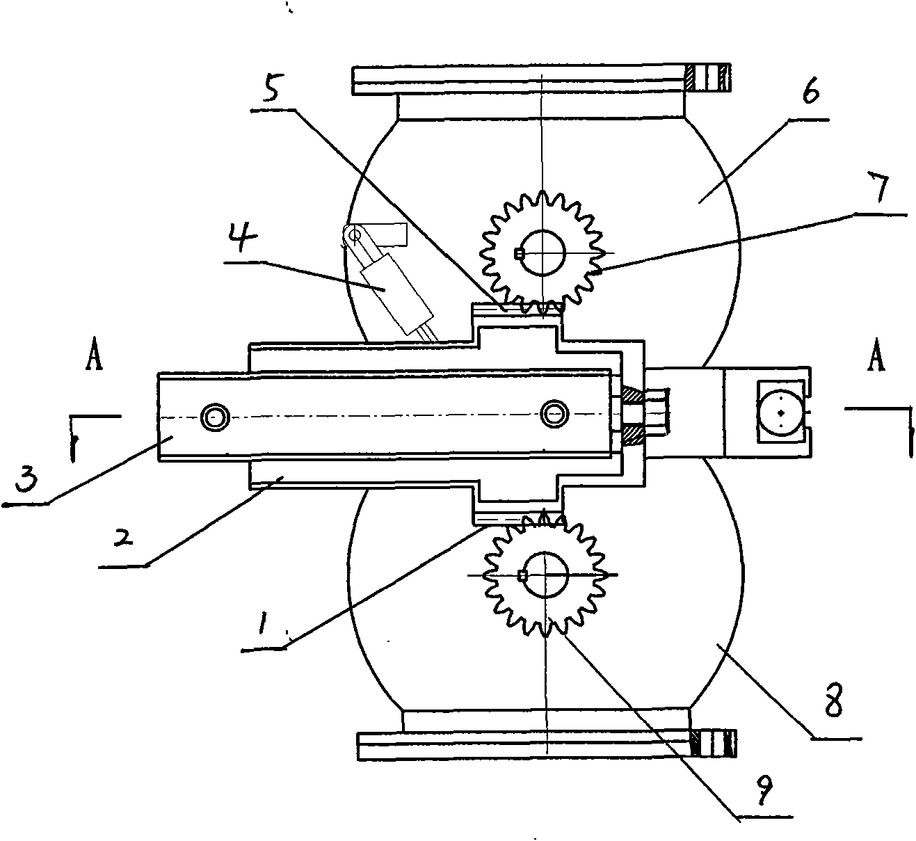
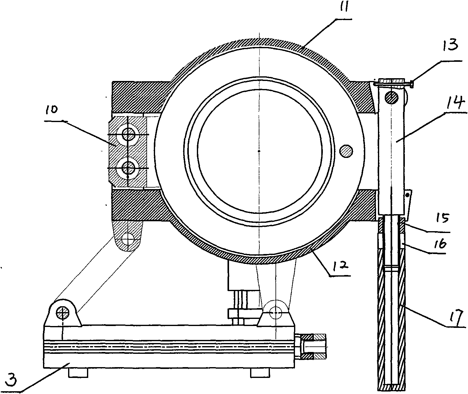
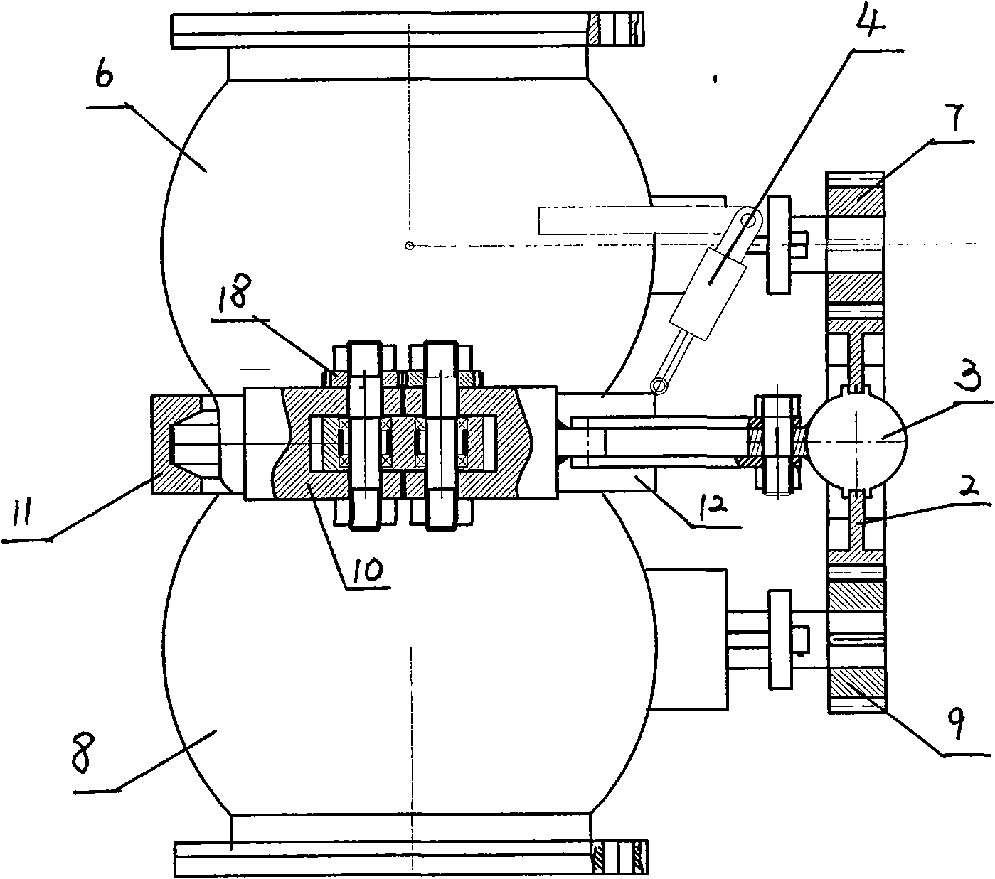
[0014] An emergency release device for liquid delivery, including upper and lower valve bodies 6, 8 and a locking assembly, the locking assembly includes a front clamping plate 12, a rear clamping plate 11, a clamping plate seat 10, a locking rod 14, and a locking nut 16 and gasket 15, the clamp seat 10 is fixedly arranged on the side of the upper valve body 6, and the valve core rotating rod of the upper and lower valve body is arranged on the front of the upper and lower valve body, and the end of the valve core rotating rod is equipped with The transmission gear 7,9 is provided with a transmission block 2 driven by an oil cylinder 3 between the two transmission gears 7,9, and the transmission block 2 is provided with upper and lower racks 5,1 cooperating with the two transmission gears. One end of the locking lever 14 is hinged with the rear clamping plate 11 through a horizontal shaft, and the other end of the locking lever 14 is engaged in the outward jaw of the front clam...


PUM


Abstract

The invention relates to an emergency separating device for liquid transmission, which comprises an upper valve body, a lower valve body and a locking assembly, wherein a clamping plate seat of the locking assembly is arranged at the side of the upper valve body; valve core rotating rods of the upper valve body and the lower valve body are arranged at the front surfaces of the upper valve body andthe lower valve body; the end parts of the valve core rotating rods are provided with transmission gears; a transmission block driven by an oil cylinder is arranged between the two transmission gears; the transmission block is provided with an upper gear rack and a lower gear rack which are matched with the two transmission gears; a locking rod is provided with a lengthened push rod; the oil cylinder is perpendicular to the lengthened push rod of the locking rod; mutually meshed synchronous gears are installed on an articulated shaft between a front clamping plate and the clamping plate seatand between a rear clamping plate and the clamping plate seat. The locking rod is pushed by the oil cylinder, and the clamping plates are pushed so that the front clamping plate and the rear clampingplate are forcibly opened synchronously from the valve body; the two clamping plates rotate to the outside synchronously under the action of a tension spring by the rotation of the synchronous gears,and the two valve bodies are thoroughly separated, in a safe and reliable way; in addition, both the opening and the closing of valves are finished by the oil cylinder, thereby having convenient installation debugging, low labor intensity and high working efficiency.

Description

technical field [0001] The invention relates to a liquid delivery loading and unloading tool, in particular to an emergency release device used on a liquid loading and unloading arm on a wharf. Background technique [0002] The liquid medium is transferred between the shipping freighter and the wharf through the liquid loading and unloading arm. Due to wind and waves or unpredictable reasons, the freighter will drift away from the normal working range. Although the loading and unloading arm has a certain extension distance, when it exceeds this extension distance When pulling, the phenomenon of pulling will occur, and the general pulling can damage the infusion equipment and cause the liquid to be delivered to leak; if it is serious, the liquid loading and unloading arm will collapse, causing serious accidents. [0003] The emergency disengagement device at home and abroad only has the vertical installation of the oil cylinder, and the cam drives the valve stem to rotate to ...

Claims


Application Information

Patent Timeline
Patent Type & Authority Applications(China)
IPC IPC(8): B67D5/68
Inventor 金建胜
Owner 连云港嘉安泰机械设备有限公司
Why Eureka
Try Eureka