Developing device and image forming apparatus and toner supplying method using the same

一种显影装置、显影剂的技术,应用在应用电荷图形的电记录工艺的设备、应用电荷图形的电记录工艺、仪器等方向,能够解决显影剂内压力变高、缩短显影剂寿命、加快显影剂磨损等问题,达到减少调色剂散落、减少图像模糊、改善混合性能的效果

Inactive Publication Date: 2010-02-03
SHARP KK
View PDF1 Cites 2 Cited by
  • Summary
  • Abstract
  • Description
  • Claims
  • Application Information

AI Technical Summary

Problems solved by technology

[0009] However, since the specific gravity of the toner in the developer is quite low (about one-third) compared with that of the carrier, the supplied toner is likely to float above the developer
Therefore, there is a problem in the existing circulation type developing device that if a large amount of toner is supplied from the toner hopper to the developer conveyance path, the toner is conveyed while remaining lumpy above the developer.
That is, the bulk density of the developer always changes depending on the toner concentration in the developer and the amount of electrostatic charge on the toner, but if there is no space for absorbing this change, the internal pressure on the developer will get higher
In particular, there is a problem that when the bulk density of the developer near the toner supply port becomes high, the supplied toner bridges the space around the toner supply port, causing toner clogging
[0014] On the other hand, if a stirring paddle with a high stirring capacity is provided, it is possible to improve the stirring performance and the mixing between the supplied toner and the developer, but there is still a problem that excessive stress acts on the developer, so speeding up Wear of the developer and shorten the life of the developer

Method used


Image

  • Developing device and image forming apparatus and toner supplying method using the same
  • Developing device and image forming apparatus and toner supplying method using the same
  • Developing device and image forming apparatus and toner supplying method using the same

Examples


no. 1 approach

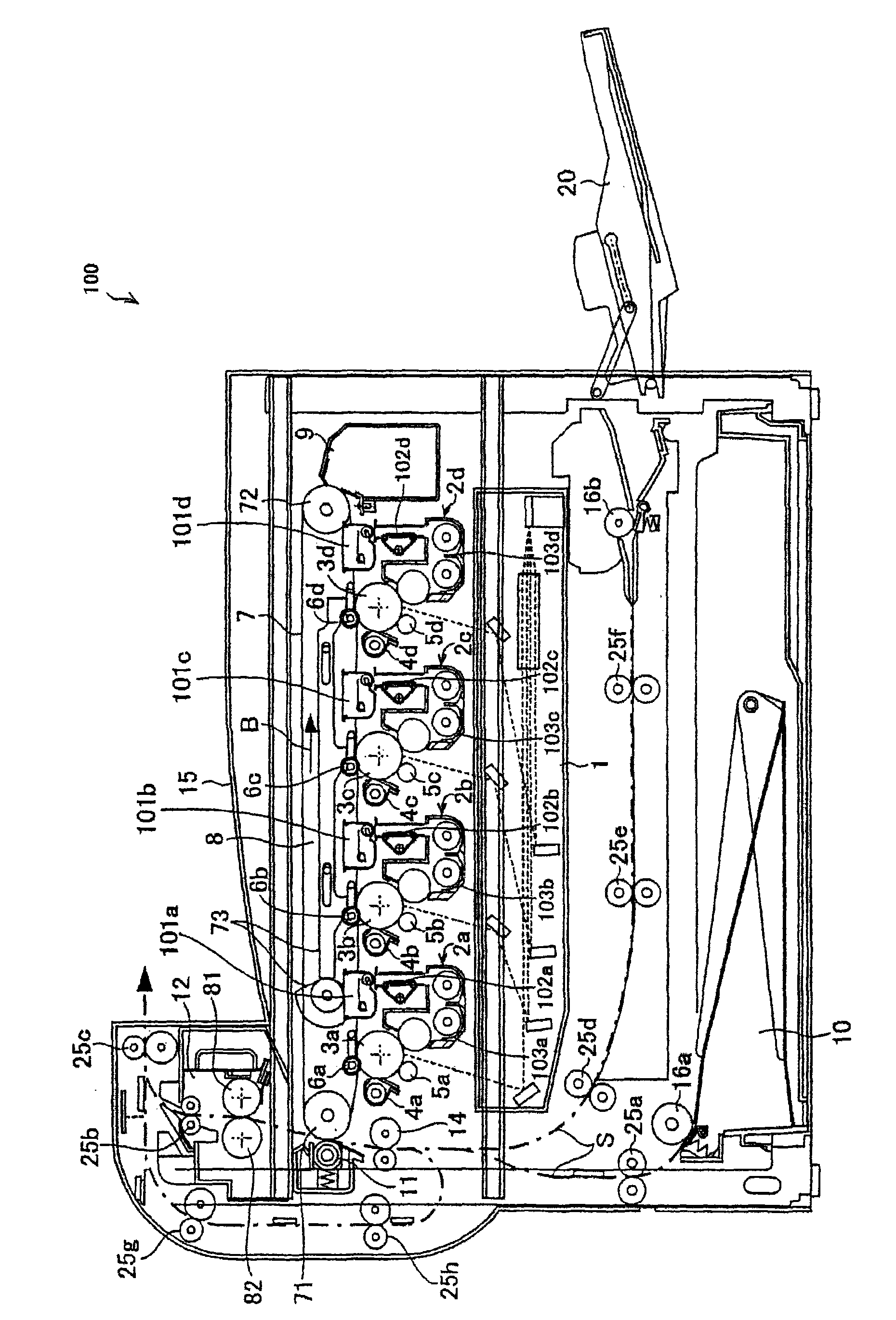
[0064] figure 1 is a schematic diagram of an exemplary embodiment of the present invention, showing the overall configuration of an image forming apparatus including the developing device according to the first embodiment of the present invention.

[0065] The image forming apparatus 100 of the first embodiment forms an image based on toner for electrophotography, including: figure 1 As shown, a photosensitive drum 3 for forming an electrostatic latent image on its surface; a charger (charging device) 5 for charging the surface of the photosensitive drum 3; an exposure unit (exposure device) 1; a developing device 2 for supplying toner to an electrostatic latent image on the surface of a photosensitive drum 3 to form a toner image; a toner for supplying toner to the developing device 2 a toner hopper (toner supply device) 101; an intermediate transfer belt unit (transfer device) 8 for transferring the toner image from the surface of the photosensitive drum 3 to a recording me...

no. 2 approach

[0128] Next, a developing device according to a second embodiment of the present invention will be described with reference to the drawings.

[0129] Figure 7 is a sectional view showing the configuration of a developing device according to a second embodiment of the present invention. Figure 8 is along Figure 7 Sectional view of plane C1-C2 cut in .

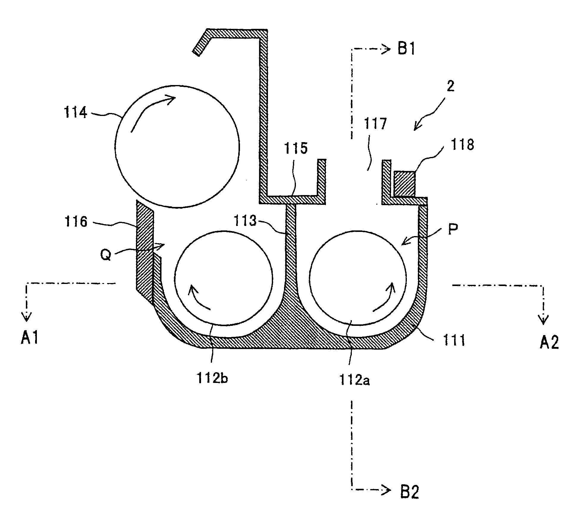
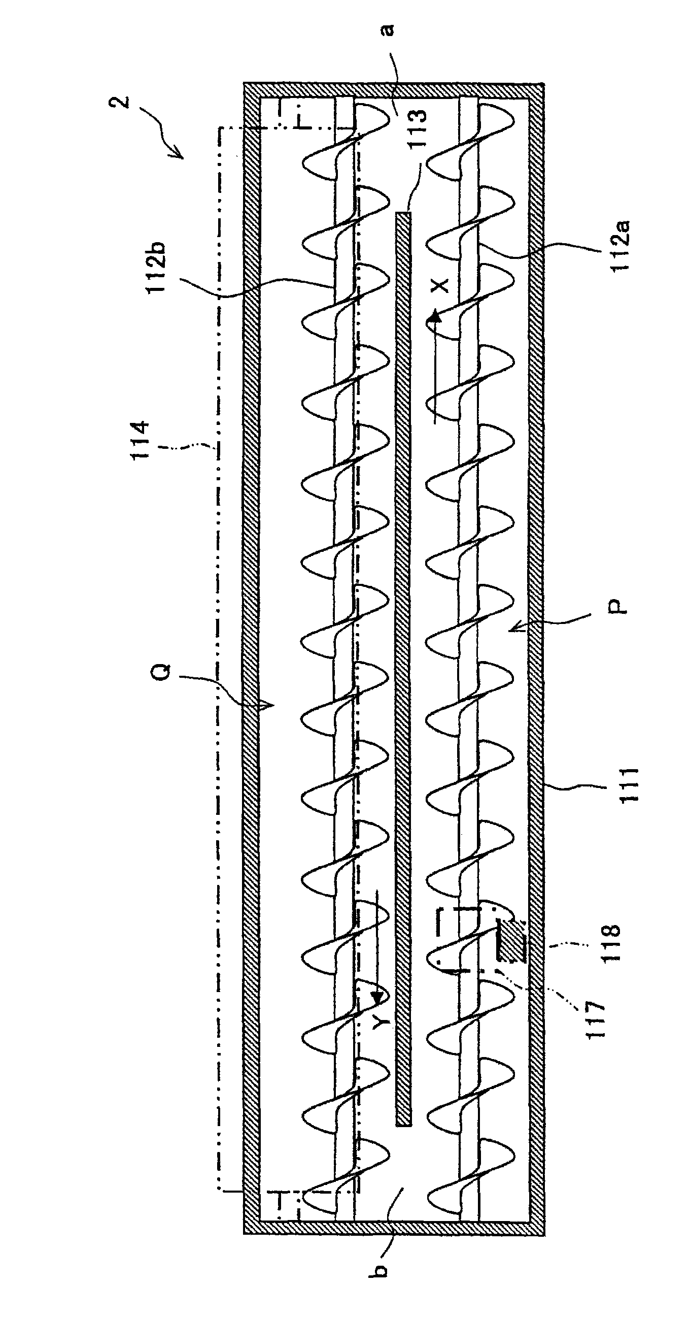
[0130] here, Figure 7 is the same as that in the developing device 2 in the first embodiment described above image 3 The corresponding sectional view, Figure 8 With Figure 4 The corresponding sectional view of the same developing device 2 in .

[0131] Such as Figure 7 and 8 As shown, the developing device 200 of the second embodiment includes: in addition to the developing roller 114, a developing container 111, a developing container cover 115, a toner supply port 117, a first conveying member 112a, a second conveying member 112b, A partition (partition wall) 113 and an electromagnet 118a.

[0132] The electr...

no. 3 approach

[0140] Next, a developing device according to a third embodiment of the present invention will be described with reference to the drawings.

[0141] Figure 11 is a sectional view showing the configuration of a developing device according to a third embodiment of the present invention. Figure 12 is along Figure 11 Sectional view cut in plane D1-D2.

[0142]Such as Figure 11 and 12 As shown, the developing device 300 of the third embodiment includes: in addition to the developing roller 114, a developing container 111, a developing container cover 115, a toner supply port 117, a doctor blade 116, a first conveying member 112a, a second Two transport members 112b, a partition (partition wall) 113, and electromagnets 118b and 118c.

[0143] The electromagnets 118b and 118c are arranged near the toner supply port 117 on the top wall of the first conveyance path P (upper inner surface of the developing container 111). More specifically, the electromagnets 118b and 118c are...


PUM


Abstract

A developing device includes: a developing vessel for storing a developer D containing a toner and a magnetic carrier; a first conveying passage for conveying the developer; a first conveying member provided in the first conveying passage for agitating and conveying the developer in a predetermined direction; a developing roller; a toner supply port for supplying toner to the first conveying passage; and an electromagnet arranged at the outer periphery of the toner supply port, and is constructed such that the toner supply port is formed over the first conveying member and the electromagnet intermittently attracts the developer residing under the toner supply port. The present invention also relates to an image forming device using the developing device and a toner supplying method.

Description

technical field [0001] The present invention relates to a developing device, an image forming apparatus using the same, and a toner supply method; in particular, to a developing device using a two-component developer containing toner and a magnetic carrier, which is applied to electrophotography-based Among image forming apparatuses using toner for image formation, such as xerographic copiers, laser printers, facsimile machines, etc., it also relates to an image forming apparatus and a toner supply method using the same. Background technique [0002] In general, electrophotography-based image forming apparatuses such as copiers, printers, facsimiles, and the like are known. An image forming apparatus using electrophotography is configured to form an image by forming an electrostatic latent image on the surface of a photosensitive drum (toner image carrier), supplying toner from a developing device to the photosensitive drum to develop the electrostatic latent image, by The ...

Claims


Application Information

Patent Timeline
Patent Type & Authority Applications(China)
IPC IPC(8): G03G15/09
CPCG03G15/0898G03G2215/0802G03G15/0839G03G15/0877G03G15/0879G03G15/0893
Inventor 明渡秀一
Owner SHARP KK
Why Eureka
Try Eureka