DC convertor

A technology of DC converter and device, which is applied in the direction of converting DC power input to DC power output, without intermediate conversion to AC conversion equipment, and output power conversion device, which can solve the problems of lower conversion efficiency, slow load response speed, and dynamic Response is not very good and other problems, to achieve the effect of small ripple and good anti-noise ability

Active Publication Date: 2010-02-03
CHENGDU MONOLITHIC POWER SYST
View PDF4 Cites 14 Cited by
  • Summary
  • Abstract
  • Description
  • Claims
  • Application Information

AI Technical Summary

Problems solved by technology

However, when the circuit 50 is running, at least three switching tubes are working at the same time, which increases the switching loss and conduction loss, thereby reducing the conversion efficiency
Moreover, when the output needs to be b

Method used


Image

  • DC convertor
  • DC convertor
  • DC convertor

Examples


Example

[0029] The first embodiment:

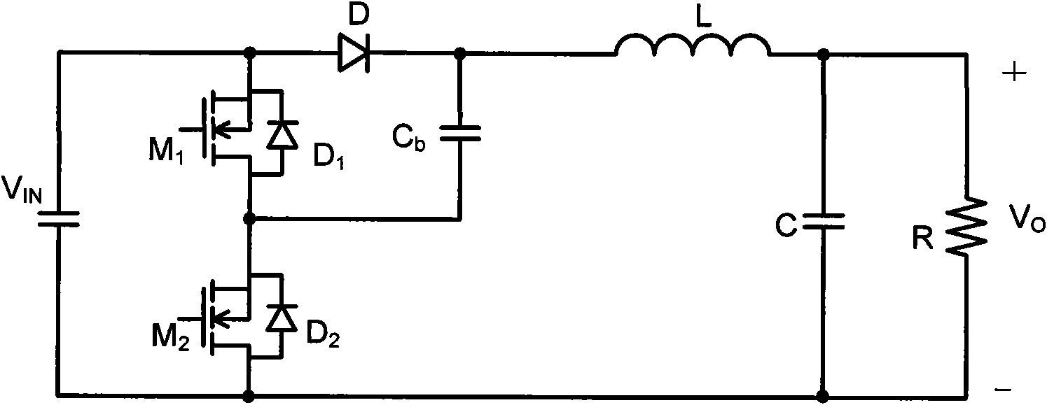
[0030] Such as Figure 4 Shown is an improved new voltage converter circuit 100 according to the present invention, which is the first embodiment of the present invention. As shown in the figure, the circuit 100 includes an input part, a first switching device S 1 , The second switching device S 2 , The third switching device S 3 , The first capacitor C 1 , The second capacitor C 2 , Inductance L 1 And load R L . The first end of the input part is connected to the first switching device S 1 The first terminal and the third switching device S 3 The first terminal, the first switching device S 1 The second terminal is connected to the first capacitor C 1 The first terminal and the second switching device S 2 The first terminal, the third switching device S 3 The second terminal is connected to the first capacitor C 1 The second terminal and the inductor L 1 The first terminal, the inductance L 1 Is connected to the second capacitor C 2 The first end an...

Example

[0034] The second embodiment:

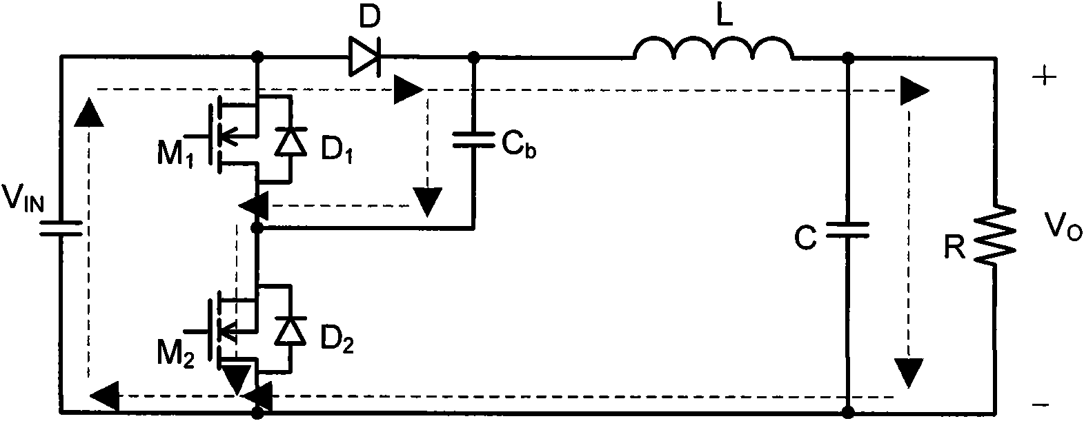
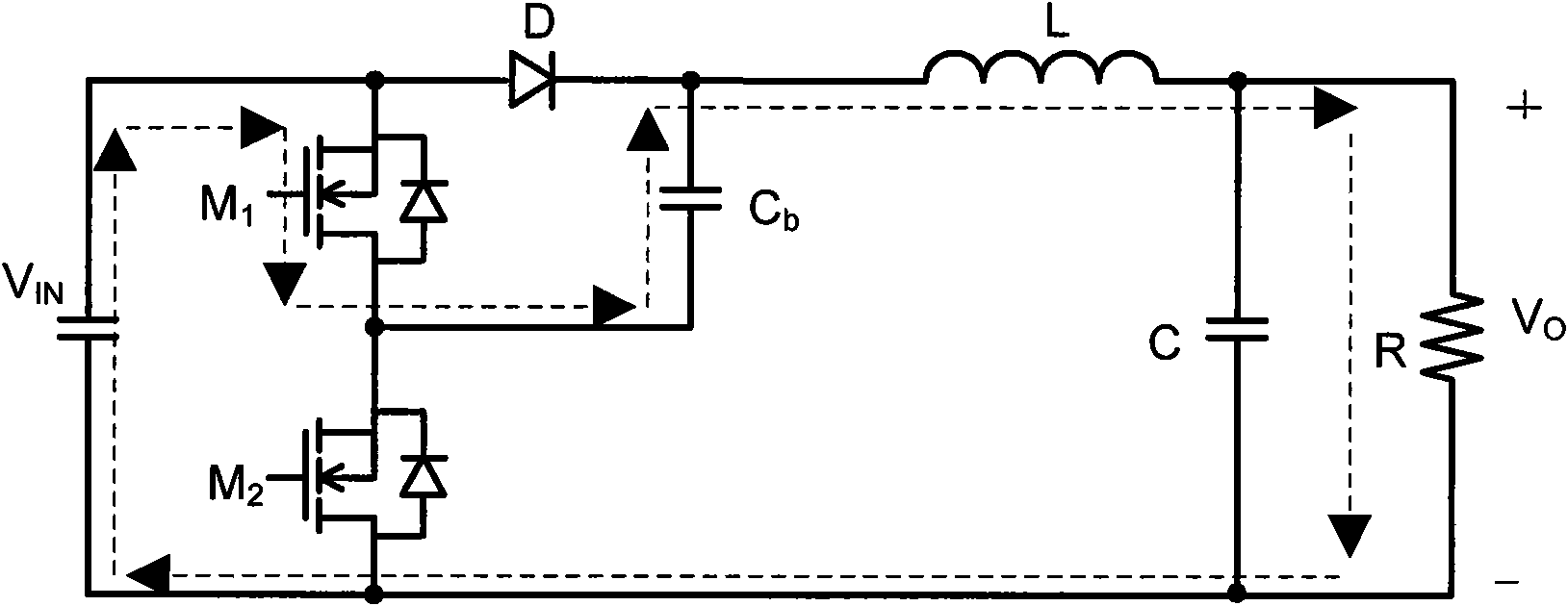
[0035] Such as Figure 5 Shown is an improved new voltage converter circuit 200 according to the present invention, which is the second embodiment of the present invention. Circuit 200 and Figure 4 The same parts use the same reference numerals, which are the same as those in the first embodiment Figure 4 The difference of the circuit 100 is that the circuit 200 also includes a third switching device S 3 The fourth switching device S between the second terminal and the ground 4 , The fourth switching device S 4 The first terminal is connected to the third switching device S 3 The second end of the fourth switching device S 4 The second terminal is grounded. Those skilled in the art should realize that the fourth switching device S 4 It can be switching devices such as diodes, triodes, MOSFETs, and IGBTs.

[0036] When the output voltage V O The requirement is between 0~V IN Within the range, the first switching device S 1 And the second switching...


PUM


Abstract

The invention provides a DC convertor, which comprises an input part, a first switch element, a second switch element, a first capacitor, a second capacitor, an inductor and a third switch element, wherein the first end of the input part is connected with the first end of the first switch element and the first end of the third switch element, the second end of the first element is connected with the first end of the second switch element and the first end of the first capacitor, the second end of the third switch element is connected with the second end of the first capacitor and the first end of the inductor, the second end of the inductor is connected with the first end of the second capacitor, and the second end of the second capacitor, the second end of the second switch element and the second end of the input part are grounded. The DC convertor has properties of small output-voltage ripple, good noise resistance and rapid loading response, the output voltage can be increased or decreased, namely, the range of the output voltage is wider, and the input and the output can be effectively cut off when required.

Description

technical field [0001] The invention relates to a DC-DC converter, in particular to a non-isolated DC-DC voltage converter. Background technique [0002] Nowadays, in many consumer electronics, communication equipment and computer power supplies, it is often necessary to convert a given voltage, especially in portable communication systems, such as MP3, Bluetooth devices, etc. In these applications, control of output voltage ripple and noise is very important. Although the traditional boost circuit has small output voltage ripple and good anti-noise ability, but because there is a zero point in the right half plane of the transfer function, the dynamic response is not very good, and the load response speed is slow. In the prior art, many circuit topologies have been improved to meet these requirements. Among them, the paper published at the APEC'07 conference - "A Novel Voltage-boosting Converter: KY Converter" (a new type of voltage-boosting converter: KY Converter ) The ...

Claims


Application Information

Patent Timeline
IPC IPC(8): H02M3/07
CPCH02M3/158
Inventor 欧阳茜
Owner CHENGDU MONOLITHIC POWER SYST
Why Eureka
Try Eureka