Die casting machine

A die-casting machine and wire technology, applied in the field of die-casting machines, can solve the problems of time required, reduced manufacturing efficiency of die-casting products, low melting efficiency, etc., and achieve the effects of improving manufacturing efficiency, improving melting efficiency, and shortening melting time.

Inactive Publication Date: 2010-02-10
MIWA LOCK COMPANY
View PDF0 Cites 9 Cited by
  • Summary
  • Abstract
  • Description
  • Claims
  • Application Information

AI Technical Summary

Problems solved by technology

[0006] However, although in the above-mentioned conventional die-casting machine, a metal block Wa of, for example, a diameter of 60 mm and a length of 70 mm is supplied in the sleeve 100, it takes time to melt it due to its block shape, and the melting efficiency becomes low. The supply port 103 on the side wall of the sleeve 100 is filled with a metal block, so the metal block is often stuck in the supply port 103, etc., resulting in unreliable supply of metal, and thus there is a problem that the manufacturing efficiency of die-casting products is reduced.

Method used


Image

  • Die casting machine
  • Die casting machine
  • Die casting machine

Examples


Embodiment Construction

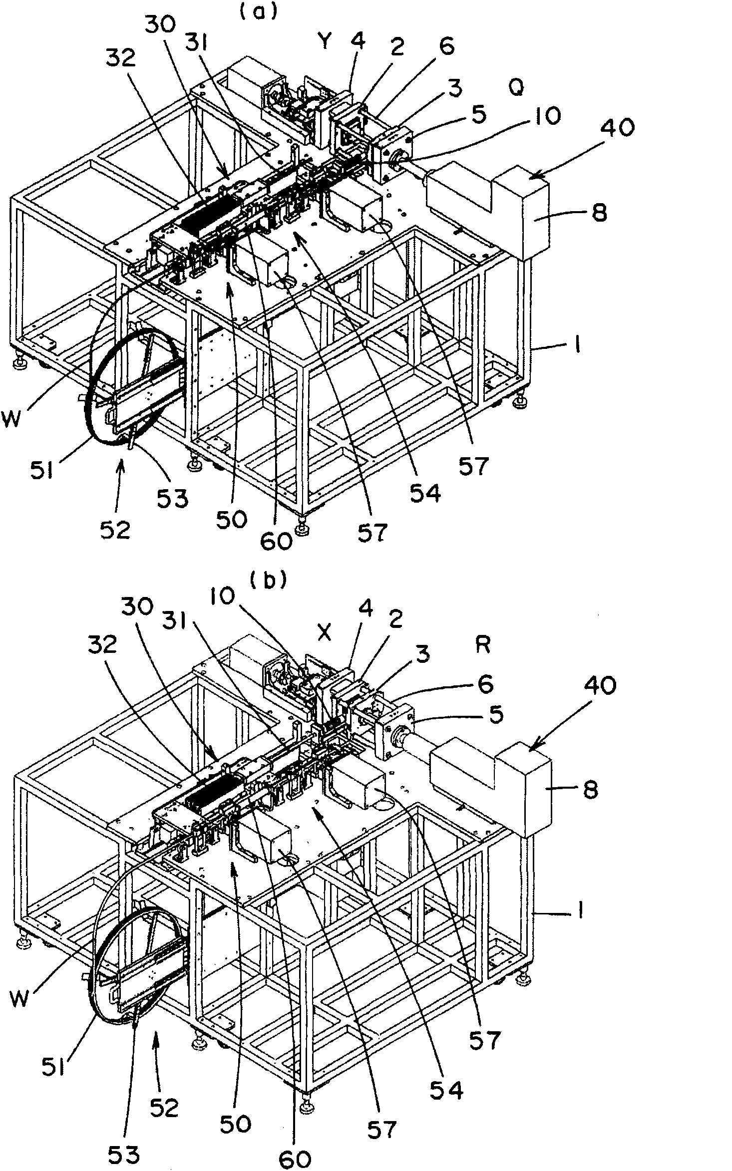
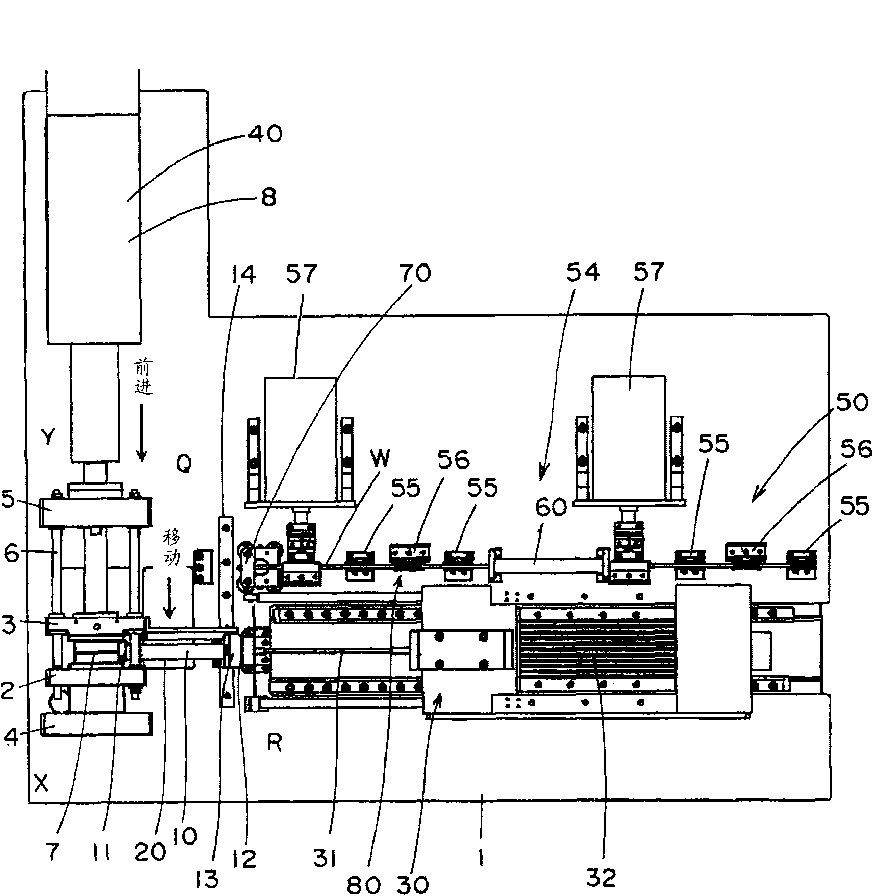
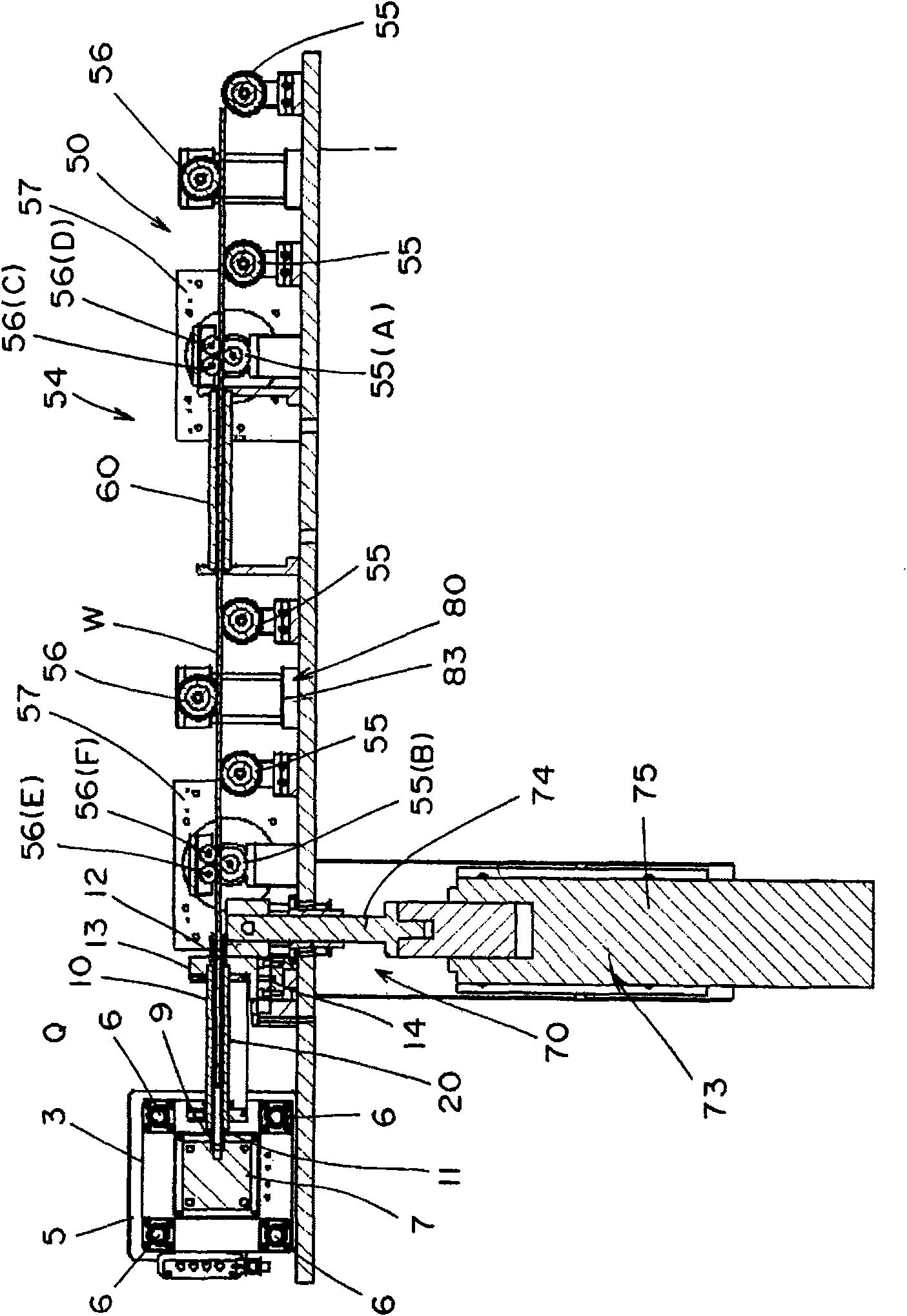
[0083] Hereinafter, a die casting machine according to an embodiment of the present invention will be described in detail based on the drawings.

[0084] Such as Figure 1 to Figure 3 As shown, the die-casting machine of this embodiment includes a chassis 1 on which a fixed mold 2 and a movable mold 3 are provided. The stent 2 is fixed on the chassis 1 via a stent support member 4 provided on the chassis 1 . The movable die 3 is slidably provided on a plurality of rods 6 temporarily installed between the fixed die support member 4 and the fixed die support member 4 fixed to the chassis 1 at a predetermined interval. . By this sliding, the movable mold 3 is engaged with the fixed mold 2 to form a cavity 7 together with the fixed mold 2, and the molten metal can be molded at the forming position X ( figure 1 (b)) or the departure position Y from the stent 2 ( figure 1 (a)) The two positions move. Further, the fixed member 5 is provided with an air cylinder device 8 driven...


PUM


Abstract

The present invention provides a die casting machine which can shorten the melting time of metal in a sleeve, shorten the melting efficiency and reliably supply metal into the sleeve thereby increasing the manufacturing efficiency of the die casting product. The die casting machine comprises the following components: a cylindrical sleeve (10) which is provided an ejection opening (11) communicatedwith the casting inlet of a die cavity (7) at one end and is provided an insertion opening (12) being inserted with metal wire (W) with a preset length; a heating part (20) which is provided at the outside of the sleeve and is provided with a high-frequency coil for melting the metal wire that is inserted into the sleeve for a preset length at a derivation position (Y) of the movable die (3) relatively to the fixed die (2); and an ejection part (30) which is provided with a piston (31) which can be inserted from the insertion opening of the sleeve and cause the molten metal in the sleeve to eject from the ejection opening at a forming position (X) of the movable die relatively to the fixed die.

Description

technical field [0001] The present invention relates to a die-casting machine that injects heated and molten metal into a desired shape, and particularly relates to a die-casting machine that melts and injects a predetermined amount of metal immediately before the injection. Background technique [0002] Conventionally, as such a die-casting machine, for example, a technology disclosed in Japanese Patent No. 2703675 (Patent Document 1) is known. [0003] Such as Figure 11 As shown, such a die casting machine includes a fixed die (not shown) and a movable die (not shown) forming a cavity in which molten metal is formed together with the fixed die. This die-casting machine structure includes: a cylindrical sleeve 100, which has an injection port 101 communicating with the casting inlet of the cavity at one end, and a supply port 103 for supplying a predetermined amount of metal block Wa on a side wall 102 at the other end side. The heating part 104 is provided on the outside...

Claims


Application Information

Patent Timeline
IPC IPC(8): B22D17/04B22D17/28B22D17/32B22D17/20B21F11/00
Inventor 北方秀和谷坂裕
Owner MIWA LOCK COMPANY
Why Eureka
Try Eureka