
Balancing weight handling device and movable crane

A technology for mobile cranes and loading and unloading devices, which is applied in the direction of cranes and hoisting devices, and can solve problems such as unreasonable force on the turntable, affecting the stability of mobile cranes, and increasing the size of mobile cranes

Inactive Publication Date: 2010-02-10
SANY AUTOMOBILE MFG CO LTD
View PDF0 Cites 29 Cited by
  • Summary
  • Abstract
  • Description
  • Claims
  • Application Information

AI Technical Summary

Problems solved by technology

[0007] The balance weight loading and unloading mechanism of this structure sets the left lift cylinder, right lift cylinder, left lock cylinder, and right lock cylinder on the turntable of the mobile crane. The volume of each component of the large tonnage and super large tonnage mobile crane itself They are all relatively large. In order to ensure that the overall size of the mobile crane does not exceed the road driving standard, the components are arranged in a compact manner, and the space between the components is very limited. If the left lifting cylinder, right lifting cylinder, and left locking cylinder are installed on the turntable The oil cylinder and the right locking cylinder will cause the space on the turntable to be very narrow, which will affect the normal rotation of the turntable and seriously affect the working performance of the mobile crane; at the same time, due to the left lift cylinder, right lift cylinder, left lock cylinder, right The locking cylinders all have a large weight. If their positions are not set properly, the force on the turntable will be unreasonable, which will seriously affect the stability of the mobile crane; moreover, the left lifting cylinder, the right lifting cylinder, and the left locking cylinder , the right locking oil cylinder has a larger size, which will increase the size of the mobile crane vehicle, so that the overall size of the mobile crane will exceed the road driving standard

Method used


Image

  • Balancing weight handling device and movable crane
  • Balancing weight handling device and movable crane
  • Balancing weight handling device and movable crane

Examples


Embodiment Construction

[0031] The core of the present invention is to provide a counterweight loading and unloading device. The setting position of the counterweight loading and unloading device is more reasonable, so that there is enough space on the turntable of the mobile crane and the structure is more compact. Another core of the present invention is to provide a mobile crane.

[0032] The content of the present invention will be described below in conjunction with the accompanying drawings. The following description is only exemplary and explanatory, and should not have any limiting effect on the protection scope of the present invention.

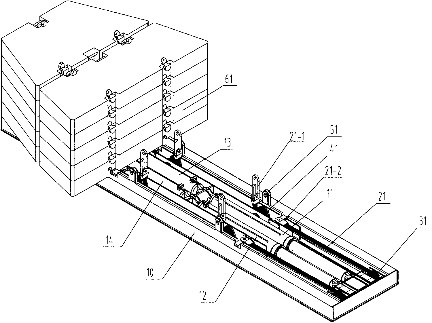
[0033] Please see figure 1 , figure 1 It is a three-dimensional structure schematic diagram of a specific embodiment of the balance weight loading and unloading device provided by the present invention.

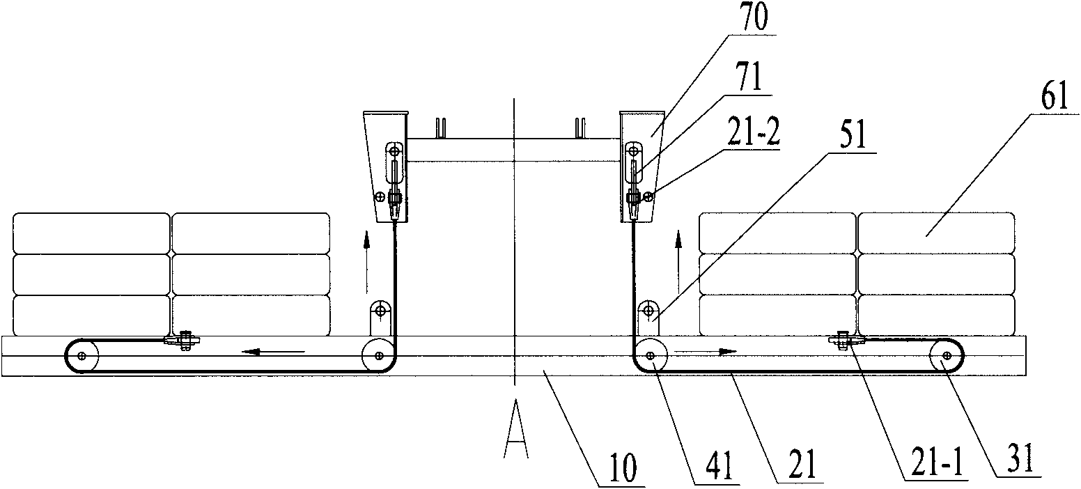
[0034] Such as figure 1 As shown, the balance weight loading and unloading device provided by the present invention includes an independently provided ...


PUM


Abstract

The invention relates to the technical field of cranes and discloses a balancing weight handling device comprising an independently arranged tray, wherein, the upper end surfaces of two ends of the tray are used for placing a balancing weight, two ends of the tray are both provided with a cavity, at least one telescopic oil cylinder is arranged in the cavity, the fixed end of the telescopic oil cylinder is fixed with the tray, and the telescopic end of the telescopic oil cylinder is used for connecting with a tray hoisting mechanism used for hoisting the tray. The balancing weight handling device with the structure is not limited by frame plane space and rotatable table height of the movable crane, does not increase the integral size of the movable crane and ensures that the integral sizeof the movable crane does not exceed path driving standard and the structure of the integral machine is more compact; the telescopic oil cylinder can also perform the function of the balancing weight,so that the stress of the rotary table is more reasonable. The invention also provides a movable crane.

Description

technical field [0001] The invention relates to the technical field of cranes, in particular to a balance weight loading and unloading device, and also relates to a mobile crane with the above-mentioned balance weight loading and unloading device. Background technique [0002] Cranes are a commonly used construction machinery. Cranes mainly include rail cranes and non-rail and mobile cranes. Mobile cranes include all-terrain cranes, tire cranes, and crawler cranes. Mobile cranes have the advantages of good passability, flexible maneuverability, fast driving speed, quick transfer, and can be put into work immediately after arriving at the destination, so they are widely used in engineering construction. However, compared with the rail crane, the mobile crane is limited by its own weight, and its lifting capacity is small. In order to improve the stability of the mobile crane under working conditions, a counterweight is usually installed on the mobile crane. [0003] The bala...

Claims


Application Information

Patent Timeline
Patent Type & Authority Applications(China)
IPC IPC(8): B66C23/72B66F9/02B66F3/28B66C23/36
CPCB66C23/74
Inventor 刘会敏刘木南张鑫
Owner SANY AUTOMOBILE MFG CO LTD
Learn More