Apparatus for coupling an element to the eye

A technology of eyes and components, applied in tonometer, ophthalmic surgery, laser surgery, etc., can solve problems such as damage

Inactive Publication Date: 2010-02-10
WAVELIGHT GMBH
View PDF8 Cites 9 Cited by
  • Summary
  • Abstract
  • Description
  • Claims
  • Application Information

AI Technical Summary

Problems solved by technology

Mechanical forces acting on the eye during laser treatment can be affected by mechanical forces generated by head movement and cause injury

Method used


Image

  • Apparatus for coupling an element to the eye
  • Apparatus for coupling an element to the eye
  • Apparatus for coupling an element to the eye

Examples


Embodiment Construction

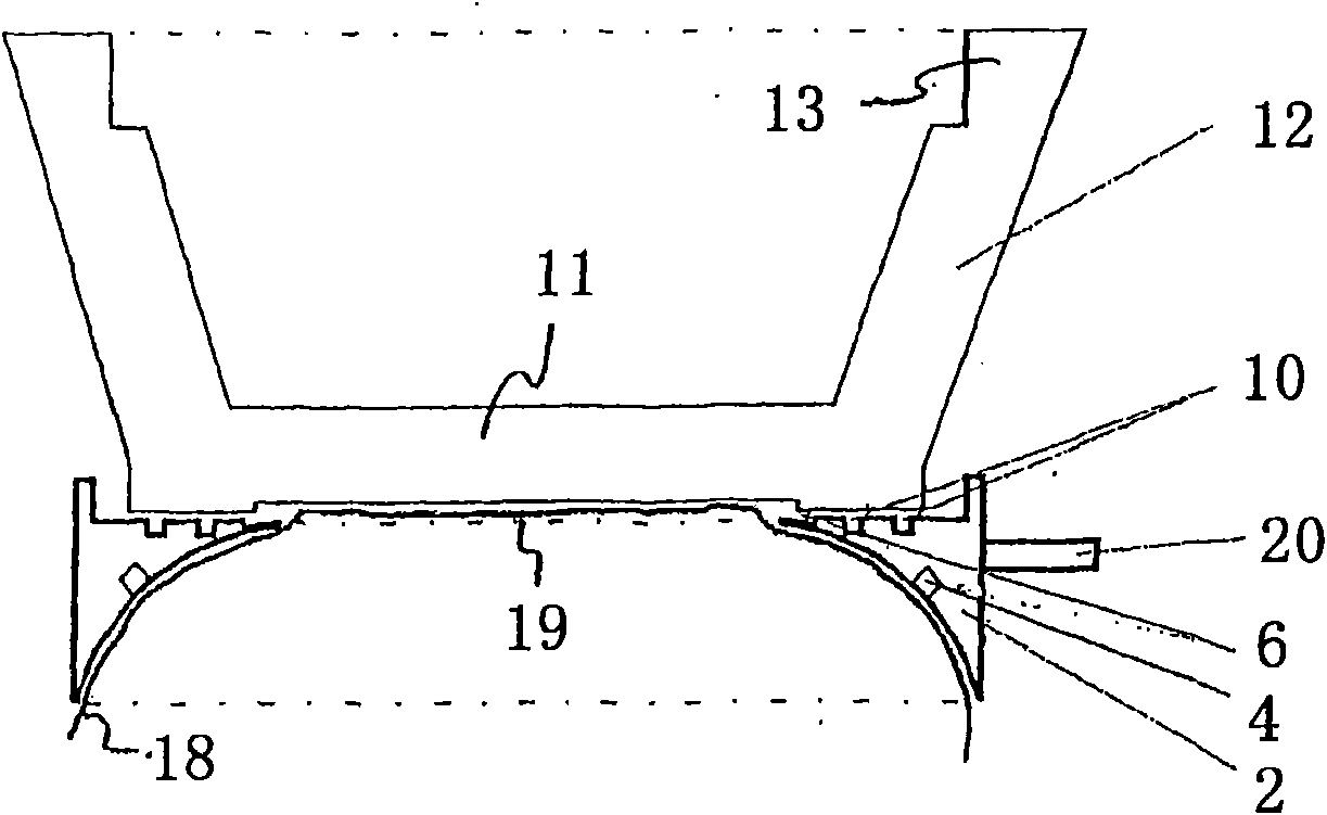
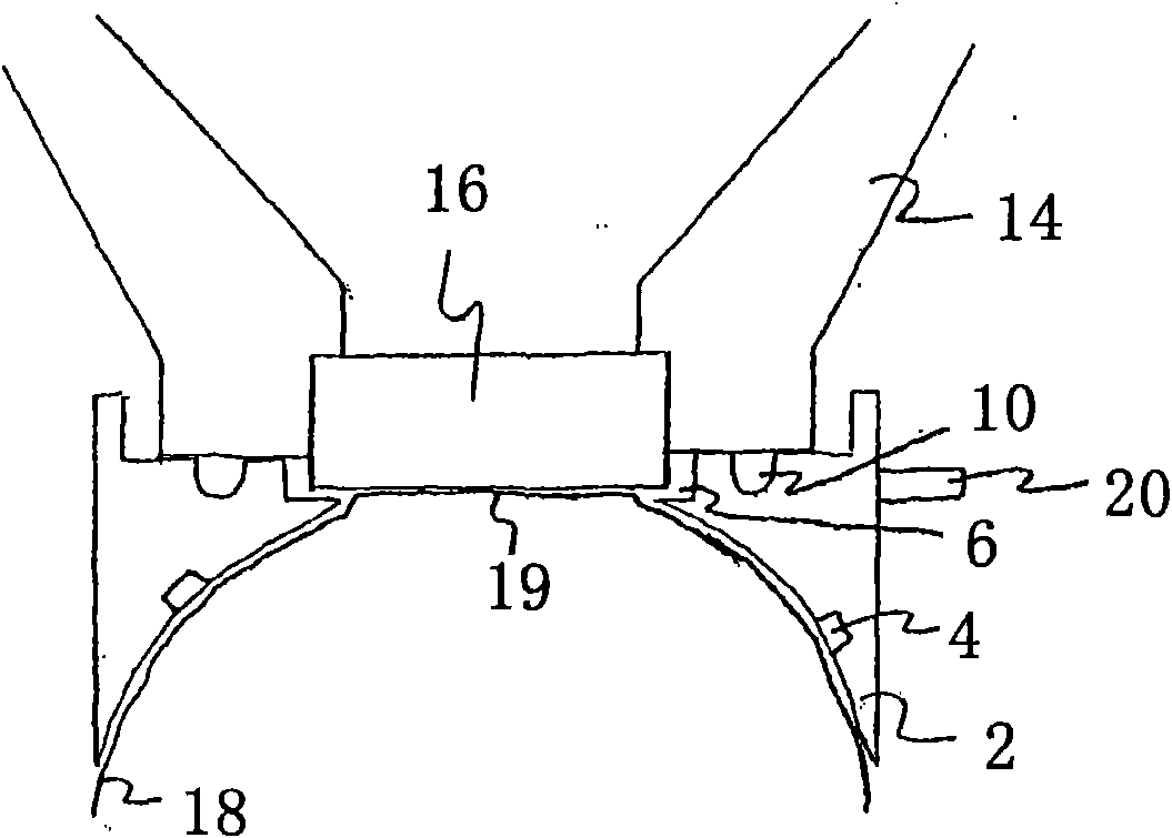
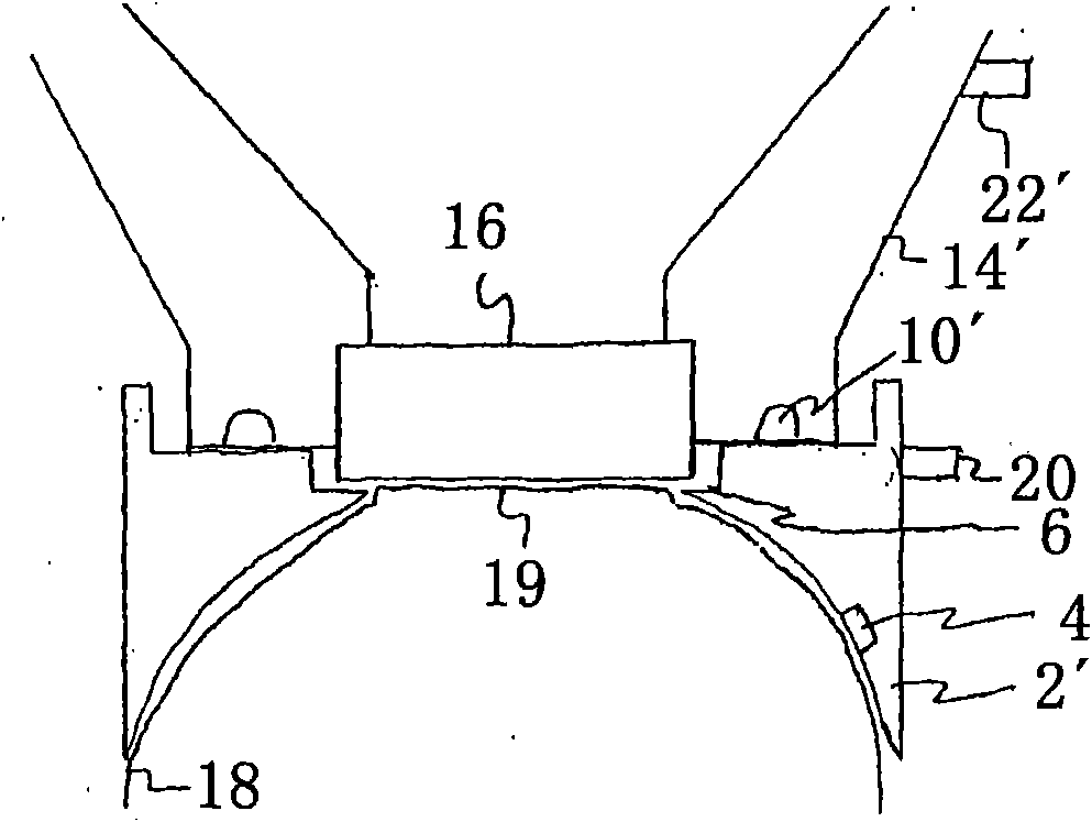
[0044] figure 1 Shown is an eye suction device 2 with a first suction area 4 designed to suck the eye suction device 2 onto the eye 18 in use, with a second suction device 10 designed to For pumping the functional element 12 in use. The functional element 12 comprises an optical element 11 which is designed as a lens or as a plate 11 . Furthermore, the functional element 12 also includes an interface region 13 via which the functional element can be connected to an optical device (not shown) of a laser system, for example a petasecond laser system.

[0045] In addition, the eye suction device also includes a third suction area, which is in fluid connection with the space between the functional element 12 and the cornea 19 of the eye 18 and at least partially evacuates the space, so that at least a part of the cornea is attached to the space. against the functional element 12 . The area against which the cornea 19 rests can be designed as a cornea-flattening lens or as a cor...


PUM


Abstract

The invention relates to a suction ring (4) for ophthalmological surgery, having a first suction region (6) that is configured to suction the suction ring onto an eye (18), and having a second suction region (10) that is configured to suction on a functional element (13). The functional element, and / or or the suction ring may comprise a measuring means. The functional element may be configured inthe shape of a vessel such that it may receive a fluid that is located between cornea of the eye and a lens during use.

Description

technical field [0001] The invention relates to a suction ring for eye surgery having a first suction area designed for suctioning the ring to the eye and a second suction area designed for the suction function element. Background technique [0002] Pulsed laser beams are used in ophthalmic surgery, for example, to make incisions in the cornea or to ablate tissue from the cornea. The incident laser beam produces a photodisruptive or photoablative process in the corneal tissue, which results in tissue separation or removal of tissue material. Such treatment of the cornea takes place, for example, in the field of refractive methods for reducing or completely eliminating visual defects of the eye, in which the cornea is reshaped and thus changes its refractive properties. [0003] The dominant refractive method for corneal surgery is the so-called LASIK (Laser In Situ Keratomileusis). For this purpose, the cornea is cut either mechanically (by means of a vibrating shear blad...

Claims


Application Information

Patent Timeline
Patent Type & Authority Applications(China)
IPC IPC(8): A61F9/013
CPCA61F9/013A61F9/009A61B3/16A61B3/117A61F9/008A61F2009/00857A61F9/007
Inventor 米歇尔·穆罗辛米歇尔·比勒克里斯多夫·多尼茨基克里斯蒂安·威尔纳
Owner WAVELIGHT GMBH
Why Eureka
Try Eureka