Blowing interface of blowing and sucking machine

A blower and interface technology, which is applied in the direction of cleaning methods, cleaning methods and utensils, chemical instruments and methods using gas flow, etc., can solve the problems of plane cleaning before discomfort, heavy workload, cumbersome replacement and use, etc., and achieve effective It is beneficial to popularization and application, reduces production cost, and has the effects of simple and convenient preparation process

Inactive Publication Date: 2010-02-17
王鸿智
View PDF0 Cites 4 Cited by
  • Summary
  • Abstract
  • Description
  • Claims
  • Application Information

AI Technical Summary

Problems solved by technology

The existing blower has entered the situation of hand-push operation, but due to different terrain conditions, the trolley cannot be pushed on a flat lawn, and can only rely on accessories such as extension pipes for supplementary cleaning
For more complex terrain conditions, and it is not suitable for cleaning the plane first, and then cleaning the details, users often need to frequently replace the nozzles of peripheral components (extension pipes, blowing booster nozzles) that are connected to the exhaust pipe of the blower
However, the existing traditional blower interface generally adopts the structural design of buckle butt joint, which makes the replacement and use quite cumbersome, and brings great inconvenience to the heavy workload of leaf cleaning.

Method used


Image

  • Blowing interface of blowing and sucking machine
  • Blowing interface of blowing and sucking machine
  • Blowing interface of blowing and sucking machine

Examples


Embodiment 1

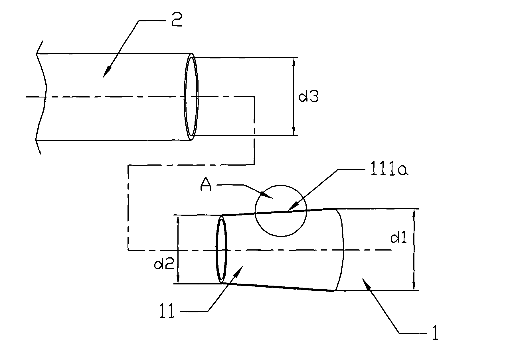
[0018] Such as figure 1 and Figure 1a As shown, the end of the exhaust pipe 1 of the blower is processed into a tapered pipe 11, that is, the outer diameter is tapered along the air outlet direction, and the diameter difference between the largest outer diameter d1 and the smallest outer diameter d2 is greater than 5mm. Moreover, the nozzle 2 of the extension pipe or blowing booster nozzle that is used to connect with the exhaust pipe 1 is designed to have no change in inner diameter, and its inner diameter d3 is between the maximum outer diameter d1 and the smallest outer diameter d2 of the tapered pipe. between.

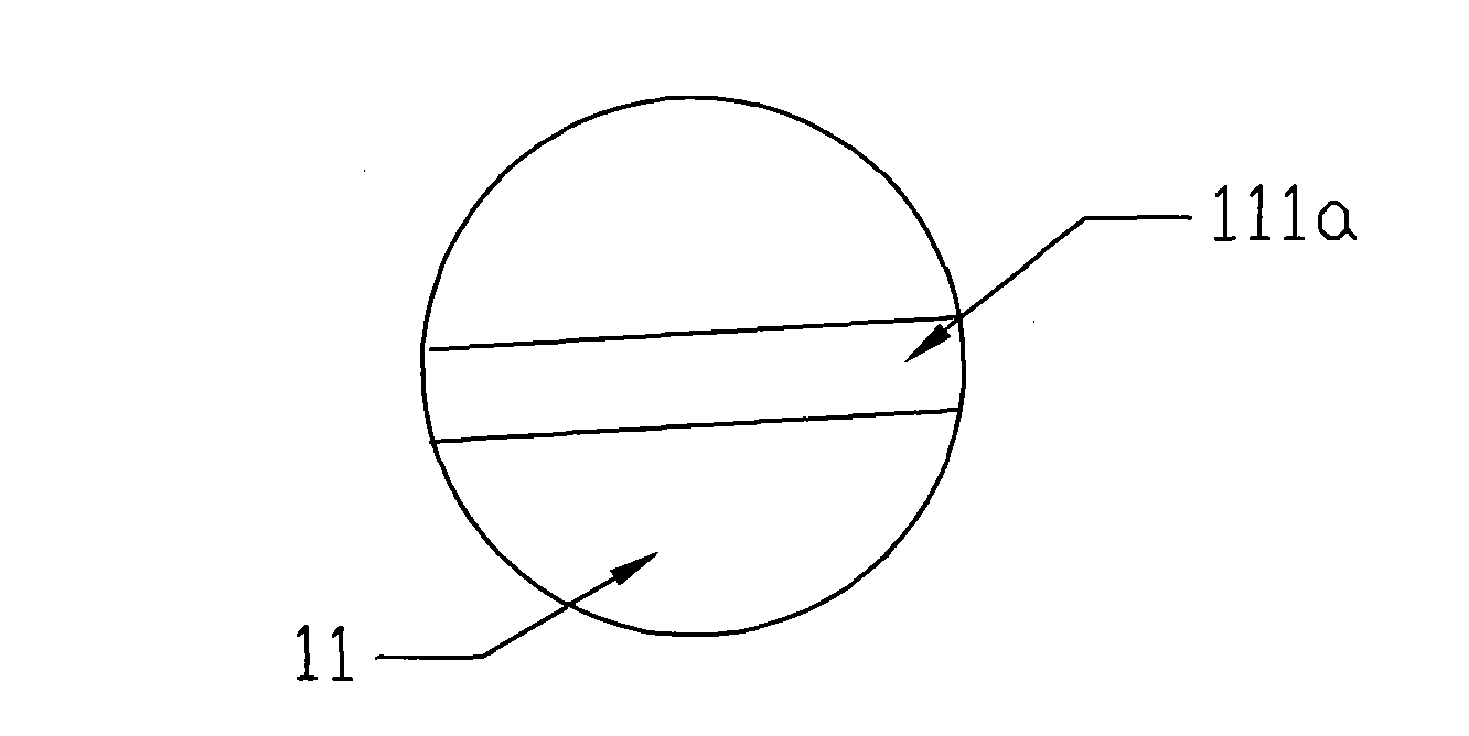
[0019] It can also be seen from the figure that the contact damping layer 111a of rubber material is distributed on the surface of the conical tube 11 of this embodiment with equal thickness, so that when the nozzle 2 is sleeved on the conical tube 11, the The contact damping layer 111a is tightly bonded, and even through a simple direct insertion method, the te...

Embodiment 2

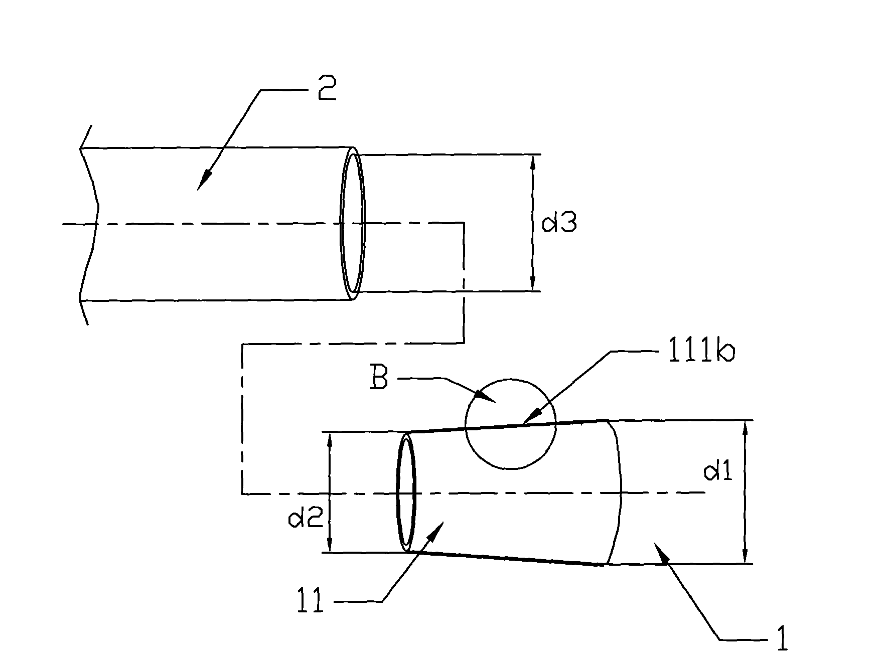
[0021] Such as figure 2 and Figure 2a As shown, the overall structure of this preferred embodiment is roughly the same as that of Embodiment 1, especially the characteristic structure is also processed into the form of a tapered pipe 11 at the end of the exhaust pipe, and the pipes of optional components are externally connected by means of direct insertion. Port 2, and the surface of the conical tube 11 is also distributed with a contact damping layer on the entire circumference. The difference is that the contact damping layer 111b made of polyester is designed to be non-uniform in thickness, and its thickness increases step by step as the outer diameter of the tapered tube 11 increases (d2→d1).

[0022] In this way, when the nozzle 2 is sleeved on the tapered tube 11, it can be sealed and fastened by the continuously thickened contact damping layer 111b, even through a simple direct plug-in method, a tight joint can still be obtained. The technical effect is high, and t...


PUM


Abstract

The invention discloses a blowing interface of a blowing and sucking machine in the field of mechanical interfaces, and the blowing interface is used for connecting an exhaust pipe of a blower and a pipe port of an extension pipe or a blowing and pressurizing nozzle. The invention is characterized in that the tail end of the exhaust pipe of the blower is in a taper pipe structure, and the inner diameter of the pipe port used for butt joint is ranged from the minimum outer diameter to the maximum outer diameter of the taper pipe; moreover, the outer surface of the taper pipe or the inner surface of the butt jointed pipe port at the tail end of the exhaust pipe is provided with a contact damping layer made of rubber or polyester. In the technical scheme of the invention, the pipe port at thetail end of the exhaust pipe is designed into a taper pipe, and is directly spliced and engaged with a pipe port of an external butt jointed component, so that the functions of the blowing and sucking machine can be conveniently and effectively switched, and the convenience of the use of the blowing and sucking machine is improved. In addition, the taper pipe structure and a preparation process thereof are simple and convenient, can effectively reduce the production cost and are beneficial to popularization and application.

Description

technical field [0001] The invention relates to a hose interface, in particular to an interface used for the butt joint work between the exhaust pipe of a blower and suction machine and peripheral accessories. Background technique [0002] The blower is an outdoor cleaning tool, mainly used for cleaning and collecting fallen leaves. It blows the leaves away by blowing air, or crushes the leaves by suction and puts them in bags. The existing leaf blower is increasingly designed towards the direction of multi-functional integration. By simply adding or reducing equipment components, the blower can be used to clean fallen leaves under various terrain conditions. The existing blowing and suction machines have entered the situation of hand-push operation, but due to different terrain conditions, the trolley cannot be pushed on a flat lawn, and can only rely on accessories such as extension pipes for supplementary cleaning. For relatively complex terrain conditions, and it is not...

Claims


Application Information

Patent Timeline
Patent Type & Authority Applications(China)
IPC IPC(8): B08B13/00B08B5/04
Inventor 王鸿智
Owner 王鸿智
Why Eureka
Try Eureka