Dustproof structure of machine tool

A dust-proof structure and machine tool technology, applied in the direction of manufacturing tools, wood processing utensils, work accessories, etc., can solve the problems of difficult cleaning, scattered cutting dust, poor dust suction effect, etc., to avoid the effect of spreading outward

Active Publication Date: 2010-02-17
IDI PRECISION MACHINERY
View PDF0 Cites 5 Cited by
  • Summary
  • Abstract
  • Description
  • Claims
  • Application Information

AI Technical Summary

Problems solved by technology

[0004] 1. If the water flow is too strong, there may be concerns about damaging the workpiece
[0005] 2. Dust deposits in the water tank, it is not easy to clean
[0006] 3 Some workpieces that cannot be exposed to water (such as workpieces used in semiconductor equipment) cannot use this dustproof method
[0008] 1. Due to the fact that the dust suction pipe cannot touch the workpiece and cannot affect the automatic tool change of the cutting tool, etc., the dust suction pipe and its air inlet are far away from the machining spindle and the cutting point, resulting in poor dust collection effect good
[0009] 2. When the length of the cutting tool is very long, the air inlet is farther away from the cutting point, and the dust suction effect is even worse
[0010] 3. The cutting work area is an open space, the air flow velocity near the air inlet is fast, and the air flow velocity far away from the air inlet is slow, so that the inhalation amount of dust far from the air inlet decreases sharply, and even cannot be inhaled, while Open spaces allow cutting dust to fly around, making vacuuming less effective
[0013] In the dust-proof box, the air flow velocity close to the air inlet of the dust suction pipe is fast, and the air flow velocity far away from the air inlet is slow, so that the inhalation of dust far from the air inlet decreases sharply, and even cannot be absorbed. Inhalation, poor vacuuming
[0014] When the height of the workpiece is high, the cutting point is above the air inlet and far away from the air inlet, the cutting dust is easy to fly from the box mouth, and the dust collection effect is deteriorated.

Method used


Image

  • Dustproof structure of machine tool
  • Dustproof structure of machine tool
  • Dustproof structure of machine tool

Examples


Embodiment Construction

[0038] In order to illustrate the central idea of ​​the present invention expressed in the column of the above-mentioned content of the invention, it is expressed in specific embodiments. Various objects in the embodiments are drawn according to the proportions, sizes, deformations or displacements that are suitable for description, rather than drawn according to the proportions of actual components, which will be described first. And in the following description, similar components are denoted by the same numerals.

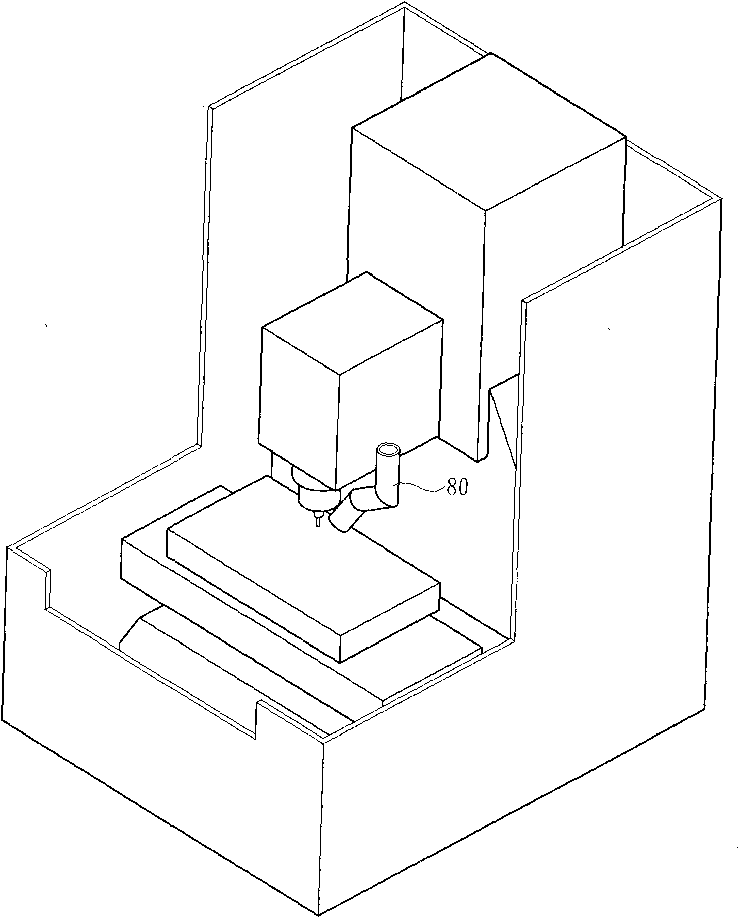
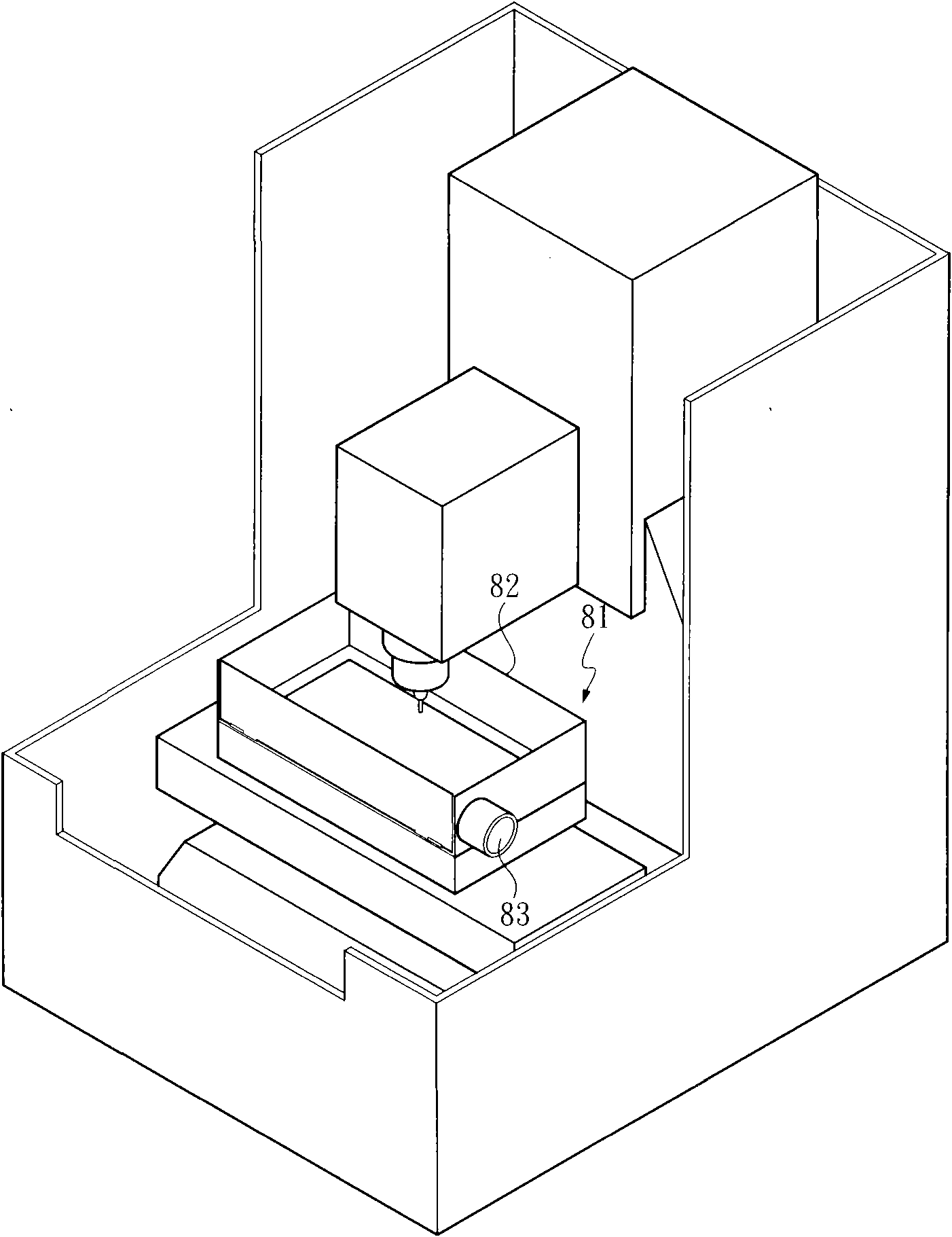
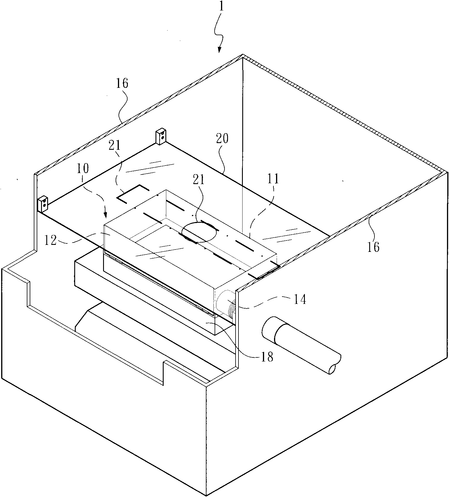
[0039] Such as image 3 , a dustproof structure comprising:

[0040] The dust-proof box 10 provided on the cutting workbench 18 of a machine tool 1 has an open box mouth 11 and a front open-close box plate 12 on the dust-proof box 10 . The cutting workpiece is located in the dustproof box 10 .

[0041] A suction pipeline 14 arranged on the side wall of the dustproof box 10 is used to connect a suction device. The suction equipment includes dust suction equipm...


PUM


Abstract

The invention discloses a dustproof structure of a machine tool, which comprises a dustproof box, an absorption pipeline and a chip-proof plate (20), wherein the dustproof box is arranged at a cuttingwork area of the machine tool and provided with an upper open box opening; the absorption pipeline is arranged on the side wall of the dustproof box and used for connecting an absorption device; andthe chip-proof plate is arranged above the dustproof box and used for shielding the upper open box opening, a small gap is reserved between the chip-proof plate and the top edge of the box wall of thedustproof box, and the chip-proof plate is provided with a main shaft hole through which a main shaft of the machine tool passes through freely. The dustproof structure of the machine tool can effectively remove dust produced during machining.

Description

technical field [0001] The invention relates to a machine tool, in particular to a dust-proof structure used to prevent dust from flying during cutting operations. Background technique [0002] It is known that materials such as graphite, wood, composite materials, ceramics and other materials are prone to generate a large amount of dust when cutting or drilling with machine tools. The dust particles are very fine, but the hardness is very high. If the dust-proof facilities are not perfect, the dust will penetrate into the In the structural system of the machine tool, it will cause damage to the machine parts or even a short circuit in the circuit system. [0003] One of the known dust-proof methods is to adopt the water curtain dust-proof method, and water forms a circular screen to surround the cutting work area, so that the cutting dust is covered by the water curtain to reduce the spillage to the outside. The running water is collected, filtered and reused. Disadvantag...

Claims


Application Information

Patent Timeline
IPC IPC(8): B28D7/02B27G3/00
Inventor 殷晓暐
Owner IDI PRECISION MACHINERY
Why Eureka
Try Eureka