Fuel injector tightening structure

A fastening structure and fuel injector technology, which is applied in the direction of machines/engines, fuel injection devices, engine components, etc., can solve the problems of high cost, difficult processing technology, complex connection structure between fuel injector and cylinder head, etc., to achieve Good assembly process, simple and reliable fastening structure, easy maintenance and inspection

Inactive Publication Date: 2010-02-17
GUANGXI YUCHAI MASCH CO LTD
View PDF1 Cites 3 Cited by
  • Summary
  • Abstract
  • Description
  • Claims
  • Application Information

AI Technical Summary

Problems solved by technology

[0004] The object of the present invention is to provide a fuel injector compact with simple structure, simple processing technology and low cost in view of the defects in the prior art that the connection structure between the fuel injector and the cylinder head is complicated, the processing technology is difficult and the cost is high. solid structure

Method used


Image

  • Fuel injector tightening structure
  • Fuel injector tightening structure
  • Fuel injector tightening structure

Examples


Embodiment Construction

[0015] The present invention will be described in detail below in conjunction with the accompanying drawings.

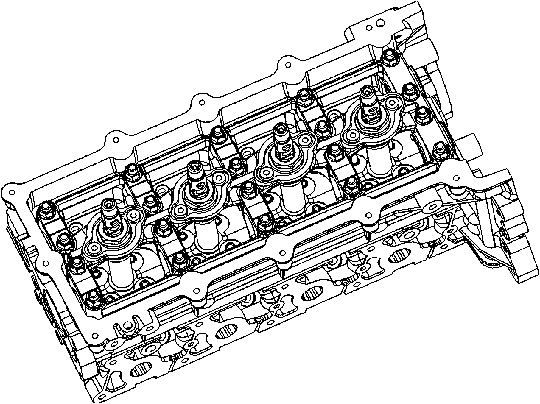
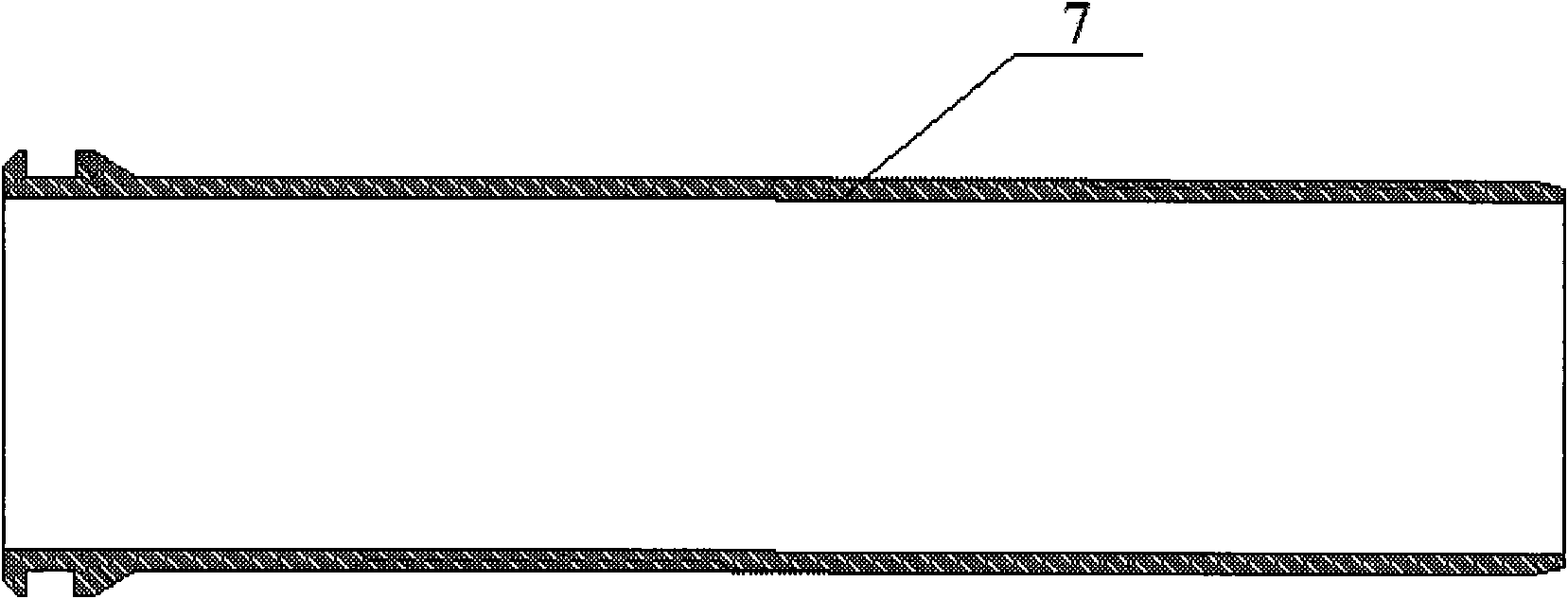
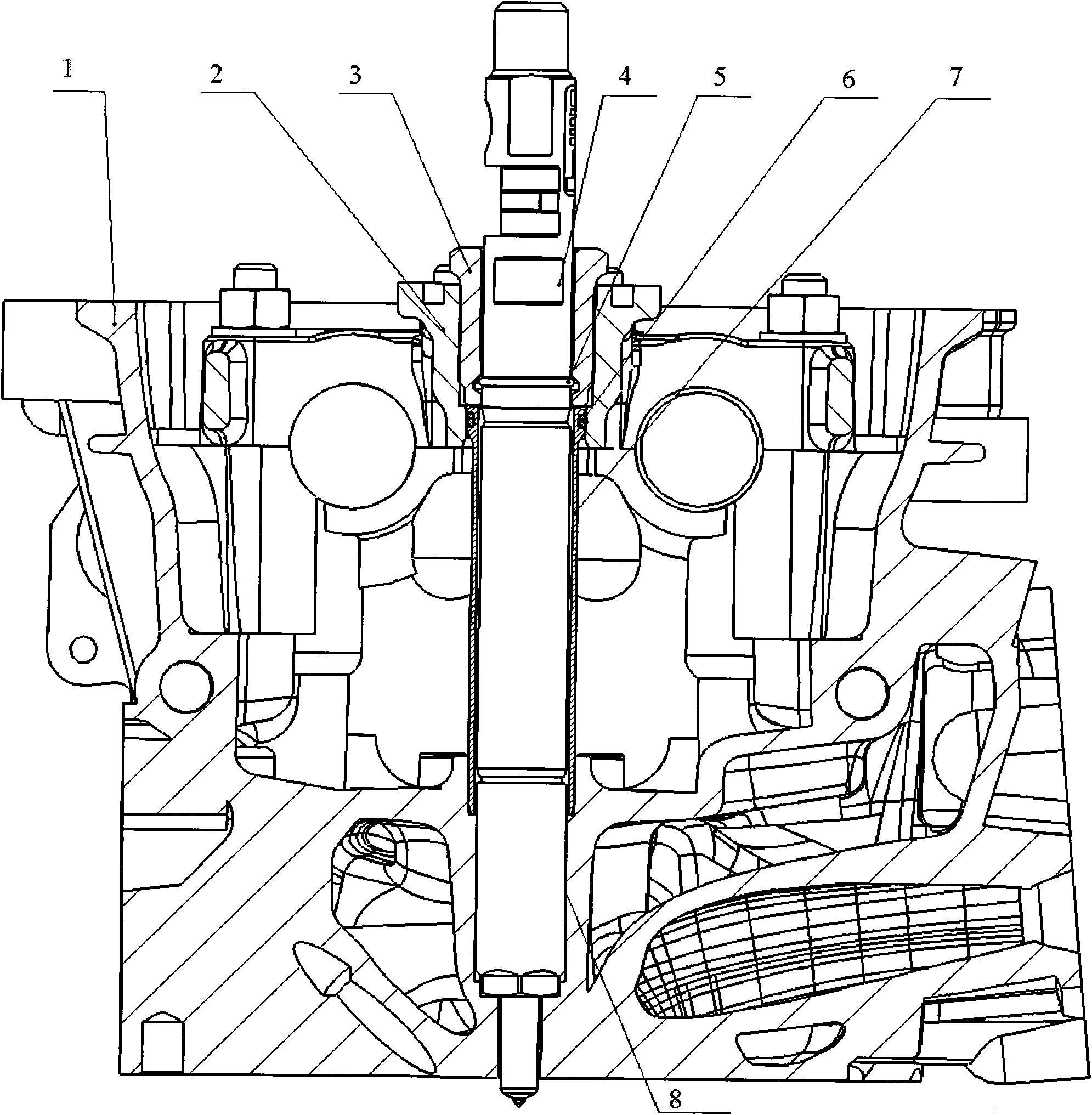
[0016] Such as Figure 1 to Figure 3 As shown, the fuel injector fastening structure of the embodiment of the present invention includes the fuel injector sleeve 7 arranged on the cylinder head 1 and the camshaft frame 2 fixed on the cylinder head 1 .

[0017] The bottom of the injector cover 7 is fixed on the cylinder head 1, and is used to seal the lubricating oil inside the cylinder head 1. The cylinder head 1 is provided with a fuel injector cover mounting hole 8, and the bottom of the fuel injector cover 7 is in interference fit with the fuel injector cover mounting hole 8. The top of the fuel injector sleeve 7 is in clearance fit with the camshaft frame 2 .

[0018] The fuel injector sleeve 7 is provided with an O-shaped sealing groove, and the fuel injector sleeve 7 is sealed and matched with the camshaft frame 2 through the O-shaped sealing ring 6, thereby ...


PUM


Abstract

The invention discloses a fuel injector tightening structure, which comprises a fuel injector sleeve arranged on a cylinder cover and a camshaft framework fixed on the cylinder cover, wherein the bottom of the fuel injector sleeve is fixed on the cylinder cover, and the top of the fuel injector sleeve is matched with the camshaft framework; and a fuel injector is arranged in the fuel injector sleeve and is connected with the camshaft framework through a tightening threaded sleeve. Aiming at the defects that in the prior art, a connecting structure of the fuel injector and the cylinder cover iscomplex, the processing technique has high difficulties and the cost is high, the whole fuel injector tightening structure is simple and reliable and has good assembling property and manufacturability; besides, because a mounting hole of the whole fuel injector does not need to be casted on the cylinder cover, a cylinder cover die can be simplified and the processing technique of the cylinder cover can be optimized, thereby reducing the production cost and simultaneously providing convenience for maintenance overhaul. The fuel injector tightening structure can be widely applied to an engine with a four-valve twin overhead camshaft structure.

Description

technical field [0001] The invention relates to an engine structure, in particular to a fuel injector fastening structure. Background technique [0002] In the prior art, for a diesel engine with a four-valve double overhead camshaft structure, components such as intake valves, exhaust valves, valve seat rings, valve springs, camshafts, and fuel injectors need to be arranged on the cylinder head, and the structure is very compact. . Among them, the fuel injector is generally arranged in the middle of each cylinder, and the fixing method of the fuel injector is usually a pressure plate pressing type. For example, the Chinese patent application number is 200510094175.4, and the patent literature titled "Diesel Engine Fuel Injector Fixing and Clamping Device" discloses a diesel fuel injector fixing and clamping device, which includes a fuel injector inserted into the cylinder head, an injector The fuel injector clip, the fastening bolt that fastens the fuel injector clip to t...

Claims


Application Information

Patent Timeline
Patent Type & Authority Applications(China)
IPC IPC(8): F02M61/14
Inventor 李金印梁保权赵增亮
Owner GUANGXI YUCHAI MASCH CO LTD
Why Eureka
Try Eureka