Brake circuit of hydraulic motor

A hydraulic motor and brake circuit technology, applied in the direction of servo motors, servo motor components, fluid pressure actuators, etc., can solve the problems of damaged pumps, hydraulic components, and difficulty in ensuring stable stop, and achieve high reliability and replacement to the smooth effect

Inactive Publication Date: 2010-02-17
陈庆桐
View PDF0 Cites 19 Cited by
  • Summary
  • Abstract
  • Description
  • Claims
  • Application Information

AI Technical Summary

Problems solved by technology

There is a problem in the parking device of this structure, that is, if the vehicle is parked on a slope, it is difficult to ensure that it stops stably only by the braking force of the spring.
The component force of the vehicle's own weight on the slope may be greater than the frictional resistance of the spring brake cylinder. At this time, the vehicle

Method used


Image

  • Brake circuit of hydraulic motor
  • Brake circuit of hydraulic motor
  • Brake circuit of hydraulic motor

Examples


Embodiment Construction

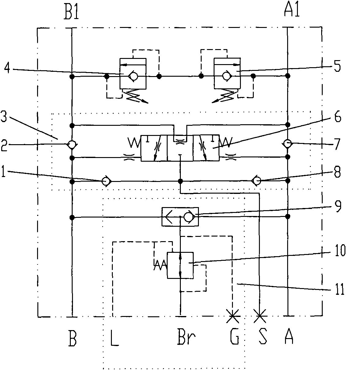
[0017] Such as figure 1 As shown, the present invention includes A oil port and B oil port connected with the power oil circuit, and A1 and B1 oil ports connected with the hydraulic motor; a brake oil circuit 11 is arranged between the A and B oil ports, and the brake oil circuit The Br port of 11 is connected to the hydraulic mechanical brake of the hydraulic motor; A1 and B1 ports are connected with a pair of relief valve B4 and relief valve A5 for adjusting the pressure of A1 and B1 ports, and it also includes a three-position three-way hydraulic valve. The control circuit 3 composed of control reversing valve 6, check valve 1, check valve 2, check valve 7, and check valve 8 has the functions of reversing and locking the oil circuit; Connect the check valve 1 set in the reverse direction, the check valve 2 2 set in the forward direction, and the three-position three-way hydraulic control reversing valve 6 near the control port on the side of the B oil port; the A oil port i...


PUM


Abstract

The invention provides a brake circuit of a hydraulic motor and relates to a brake control oil circuit of a hydraulic motor. The aim of the invention is that the hydraulic oil circuit enters a cut-offstate when stopping work, so the hydraulic motor does not drive the oil circuit to operate even though sliding down a slope, the hydraulic elements such as a pump and the like are not damaged due toreverse operation of the hydraulic motor, and simultaneously the hydraulic motor is also applied with a reverse operation resistance. The brake circuit comprises a brake oil circuit and a control circuit which is formed by a three-position three-way hydraulic control reversing valve, a one-way valve(1), a one-way valve(2), a one-way valve(7) and a one-way valve(8) and has the combined functions ofreversing and locking the oil circuit. The brake circuit has the advantages that: firstly, that power oil can reliably drive the hydraulic motor to operate is ensured; secondly, the control circuit having the combined functions of reversing and locking the oil circuit is arranged in the circuit, the automatic locking of the circuits is realized, and the pump, thehydraulic elements and the like are protected when the machine is shut down; and finally, the brake circuit ensures a crawling crane moves down along the slope at a constant speed, prevents the crawling crane from running at an accelerated speed under the action of gravity and avoids control failure.

Description

technical field [0001] The invention relates to a hydraulic drive control oil circuit, in particular to a brake control oil circuit of a hydraulic motor. Background technique [0002] At present, with the maturity of hydraulic technology, an efficient and stable hydraulic drive power source --- hydraulic motor has been born. On some large-scale engineering equipment, such as more advanced crawler cranes, hydraulic motors are used as the power source to drive them. The hydraulic motor needs a hydraulic control circuit with relatively stable performance to drive and control the hydraulic motor in use. The existing hydraulic motor and its control oil circuit can meet the general work requirements, such as ensuring its smooth advance and retreat, and can provide one way of pressure oil for the release of the hydraulic parking device after the oil circuit is activated. Large-scale construction machinery driven by hydraulic motors uses hydraulic brake cylinders and spring brake ...

Claims


Application Information

Patent Timeline
IPC IPC(8): F15B11/028F15B13/02
Inventor 陈锦富吴国余陈庆桐
Owner 陈庆桐
Why Eureka
Try Eureka