Control valve for respiratory devices

A technology for respirators and control valves, applied to respirators, etc., can solve problems such as hindering valve dynamics control, hindering operation, high frictional resistance, etc.

Inactive Publication Date: 2010-02-17
IMTMEDICAL
View PDF6 Cites 2 Cited by
  • Summary
  • Abstract
  • Description
  • Claims
  • Application Information

AI Technical Summary

Problems solved by technology

However, the large area of ​​the valve body support in the cone seat creates a high frictional resistance, which hinders the operation and hinders the dynamic control of the valve

Method used


Image

  • Control valve for respiratory devices
  • Control valve for respiratory devices
  • Control valve for respiratory devices

Examples


Embodiment Construction

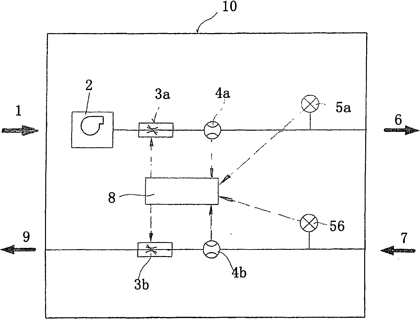
[0036] exist figure 1 The respirator shown in has an air inlet 1 and an air source 2, and the respirator has an outer cover 10 for protection. The gas source 2 is preferably designed in the form of a blower or a compressor. An internal or external pressure accumulator or an external compressed air supply can also be used as air source 2 . An adjustable inspiratory control valve 3a, an inspiratory flow sensor 4a and an inspiratory pressure sensor 5a are arranged in the upper pipeline for patient inspiratory. A suction hose 6 leading to the patient is connected to the end of the pipeline. The air outlet hose 7 is connected back to the outer cover 10 from the patient. An exhalation pressure sensor 5b, an exhalation flow sensor 4b and an adjustable exhalation control valve 3b are also arranged in the lower pipeline for controlling exhalation. The measured values ​​of the flow sensor and the pressure sensor will be continuously transmitted to the control device 8, where it will...


PUM


Abstract

The invention relates to a respiratory device for keeping a patient breathing artificially or support his or her breathing naturally. Said respiratory device comprises an air inlet, an air source, and at least one proportionally adjustable control valve. The control valve is provided with a housing (11) and a rotary valve (12) which is arranged in the housing so as to be twistable about the longitudinal axis thereof and which allows through-holes (11d) of the housing (11) to be entirely or partially closed by twisting the rotary valve (12). The rotary valve (12) and a corresponding support surface (11f) of the housing (11) have a conical shape, the support surface (11f) cooperating with the rotary valve (12). The through-holes (11d) are disposed in the area of the support surface (11f).

Description

technical field [0001] The invention relates to a valve for flow control and regulation of a respirator, wherein the valve has a housing and a rotary slide valve rotatably arranged in the housing about its longitudinal axis, by turning the rotary slide valve can be fully Or partially close at least one through-hole, the rotary slide valve has a conical sealing surface that cooperates with a correspondingly designed housing support surface, and the through-hole is arranged in the region of the sealing surface. Background technique [0002] Respirators can be used in both fixed areas (eg clinic or home) and mobile areas (eg emergency services). It is very important that the appliance operates safely, reliably and without problems. To avoid disturbing the surrounding environment when using this appliance, it must be operated as quietly and calmly as possible. [0003] US 6,615,831 discloses a respirator with a 3 / 2 bypass valve. The valve has a control slide that can be moved...

Claims


Application Information

Patent Timeline
Patent Type & Authority Applications(China)
IPC IPC(8): A61M16/20
CPCA61M16/0066A61M2016/204A61M16/20A61M2016/205A61M16/204A61M16/205A61M2016/0027
Inventor 哈里·弗里博格雅各布·戴舍尔米歇尔·威尔特费利克斯·克拉默
Owner IMTMEDICAL
Why Eureka
Try Eureka