Image prediction/encoding device, image prediction/encoding method, image prediction/encoding program, image prediction/decoding device, image prediction/decoding method, and image prediction decoding

A technology of predictive coding and predictive decoding, which is applied in image communication, television, electrical components, etc., and can solve the problems of degradation of reproduced image quality, increase of information amount, and decrease of coding efficiency.

Active Publication Date: 2010-02-17
NTT DOCOMO INC
View PDF3 Cites 35 Cited by
  • Summary
  • Abstract
  • Description
  • Claims
  • Application Information

AI Technical Summary

Problems solved by technology

[0011] In the prior art, the prediction signal of each pixel is generated by duplicating the reproduced pixel value containing distortion caused by coding (such as quantization noise), so the prediction signal also contains coding distortion
In this way, the prediction signal mixed with coding distortion becomes the main cause of the decrease in coding efficienc...

Method used


Image

  • Image prediction/encoding device, image prediction/encoding method, image prediction/encoding program, image prediction/decoding device, image prediction/decoding method, and image prediction decoding
  • Image prediction/encoding device, image prediction/encoding method, image prediction/encoding program, image prediction/decoding device, image prediction/decoding method, and image prediction decoding
  • Image prediction/encoding device, image prediction/encoding method, image prediction/encoding program, image prediction/decoding device, image prediction/decoding method, and image prediction decoding

Examples


no. 1 Embodiment approach

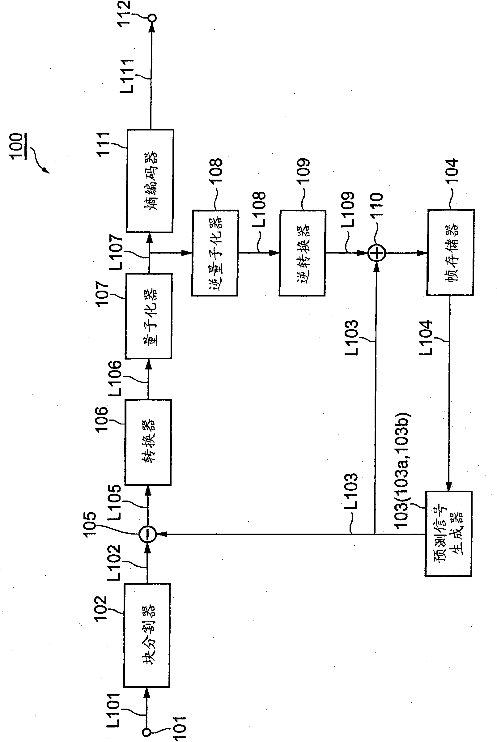
[0185] figure 1 It is a block diagram showing an image predictive encoding device 100 capable of executing an image predictive encoding method according to an embodiment of the present invention. The image predictive coding device 100 is configured to include an input terminal 101, a block divider 102 (area dividing unit), a prediction signal generator 103 (predicted signal generating unit), a frame memory 104, and a subtractor 105 (residual signal generating unit) , A converter 106 (encoding unit), a quantizer 107 (encoding unit), an inverse quantizer 108, an inverse converter 109, an adder 110, an entropy encoder 111, and an output terminal 112. The converter 106 and the quantizer 107 function as an encoding unit.

[0186] The structure of the image predictive encoding device 100 configured as described above will be described below.

[0187] The input terminal 101 is a terminal for inputting a signal of a moving image composed of a plurality of images.

[0188] The block divide...

no. 2 Embodiment approach

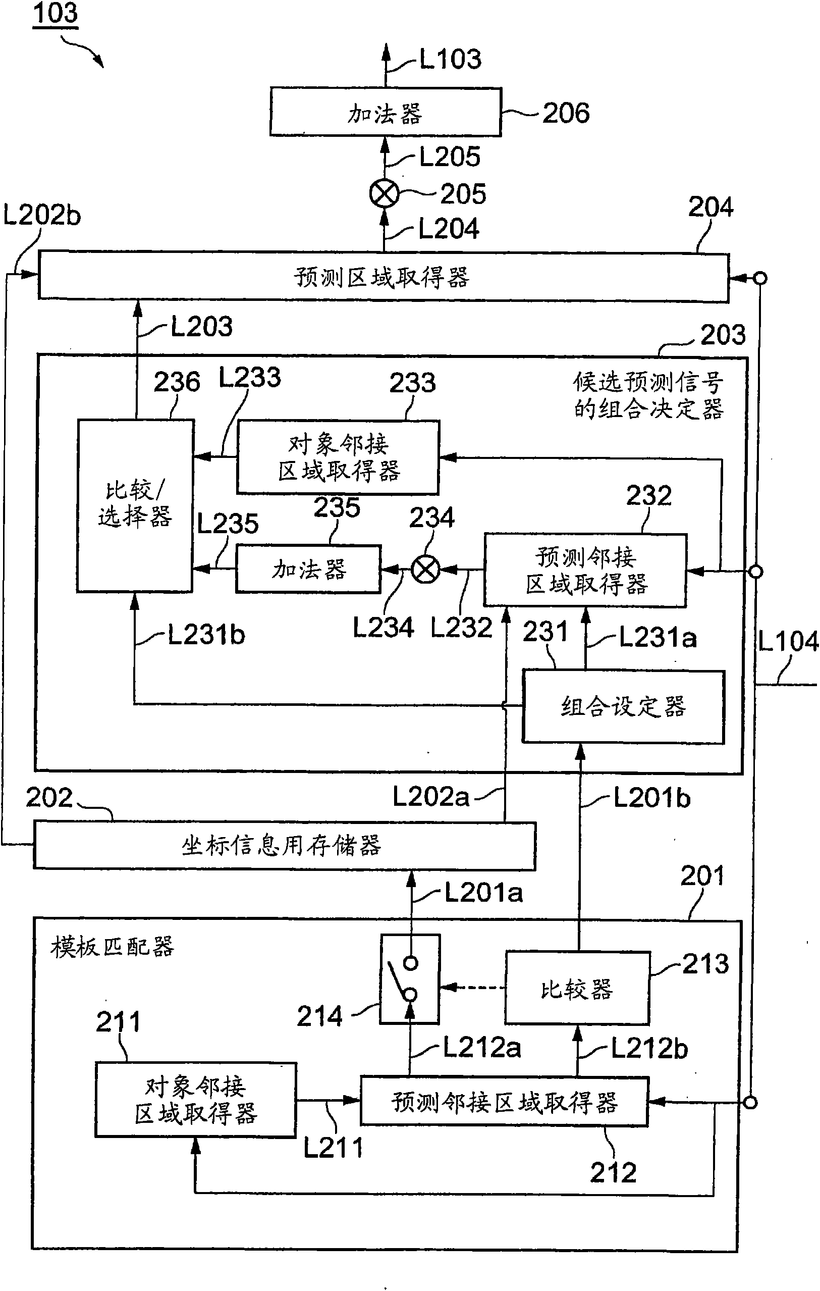
[0263] In the first embodiment, a method is shown in which the correlation between the prediction adjacent region and the target adjacent region is used to determine the candidate prediction signal (the pixel signal of the prediction region) for generating the prediction signal of the target region from a plurality of candidates. )The combination. In the second embodiment, a prediction signal generator 103a is shown that uses correlation between a plurality of candidate prediction signals to determine a combination of candidate prediction signals for generating the prediction signal of the target region from the plurality of candidates. In addition, in the second embodiment, the method of determining the combination of candidate prediction signals is not described, but the method of determining the number of candidate prediction signals is described. This embodiment shows a case where the combination of candidate prediction signals is uniquely determined based on the number of ...

no. 3 Embodiment approach

[0305] In the first and second embodiments, the description has been made on the premise that the weighted average when generating the prediction signal of the target region from a plurality of candidate prediction signals is a predetermined technique. However, if the candidate prediction signal combination selection method in the first embodiment of the present invention is used, it is possible to select from a plurality of prepared weight coefficients for each appropriate target region without additional information. This embodiment can be understood in consideration of the deformation of the drawings used in the previous description and the following description. Next, a third embodiment of the present invention will be described with reference to the deformed drawings. The drawings and descriptions overlapping with the first embodiment are omitted.

[0306] The processing of the prediction signal generator 103b of the third embodiment will be described. In addition, the pre...


PUM


Abstract

It is possible to provide an image prediction/encoding device, an image prediction/encoding method, an image prediction/encoding program, an image prediction/decoding device, an image prediction/decoding method, and an image prediction/decoding program which can select a plurality of candidate prediction signals without increasing an information amount. A weighting device (234) and an adder (235)perform a process (averaging, for example) of pixel signals extracted by a prediction adjacent region acquisition device (232) by using a predetermined synthesis method so as to generate a comparative signal for an adjacent pixel signal for each of combinations. A comparison/selection device (236) selects a combination having a high correlation between a comparison signal generated by the weighting device (234) and an adjacent pixel signal acquired by an object adjacent region acquisition unit (233). A prediction region acquisition unit (204), a weighting unit (205), and an adder (206) generate a candidate prediction signal and process it by using the predetermined synthesis method so as to generate a prediction signal.

Description

Technical field [0001] The present invention relates to an image predictive encoding device, an image predictive encoding method, an image predictive encoding program, an image predictive decoding device, an image predictive decoding method, and an image predictive decoding program, in particular to an image predictive encoding device that uses an image synthesis method to perform predictive encoding and decoding, Image predictive encoding method, image predictive encoding program, image predictive decoding device, image predictive decoding method, and image predictive decoding program. Background technique [0002] In order to efficiently transmit and accumulate still image and moving image data, compression coding technology is used. In the case of moving images, MPEG-1 to 4 or ITU (International Telecommunication Union) H.261 to H.264 are widely used. [0003] In these encoding methods, encoding / decoding processing is performed after dividing an image to be encoded into a plura...

Claims


Application Information

Patent Timeline
IPC IPC(8): H04N7/32H04N19/105H04N19/107H04N19/11H04N19/134H04N19/137H04N19/176H04N19/189H04N19/192H04N19/196H04N19/423H04N19/46H04N19/50H04N19/503H04N19/51H04N19/523H04N19/593H04N19/61H04N19/625H04N19/70H04N19/85H04N19/91
CPCH04N19/105H04N19/139H04N19/176H04N19/46H04N19/593H04N19/61H04N19/43H04N19/50
Inventor 铃木芳典文仲丞陈朝庆
Owner NTT DOCOMO INC
Why Eureka
Try Eureka