
Crush type grid

A crushing grid and blade technology, which is applied in waterway systems, drainage structures, grain processing, etc., can solve the problems of reducing the performance of the water pump, the life of the impeller of the pump, reducing the water efficiency of the grid, and affecting the performance of the grid. Cost, unlimited visual space, beautification of the surrounding environment

Inactive Publication Date: 2010-02-24
JIANGSU DATANG ENVIRONMENTAL PROTECTION ENG
View PDF0 Cites 13 Cited by
  • Summary
  • Abstract
  • Description
  • Claims
  • Application Information

AI Technical Summary

Problems solved by technology

However, the biggest threat to the downstream equipment (especially the sewage pump) in the sewage is some soft and flexible impurities, such as cloth strips, wood chips, plastic bags, rubber gloves, etc., which are easy to bypass the grille with the water flow and wind up to the pump impeller. on, thereby reducing the performance of the pump and the life of the pump impeller
These flexible impurities are also easy to wrap around the grid, block the grid gap, reduce the water passing efficiency of the grid, and affect the performance of the grid
Traditional grills capture solid waste and require manual or mechanical salvage and removal, which is likely to cause secondary pollution

Method used


Image

  • Crush type grid
  • Crush type grid
  • Crush type grid

Examples


Embodiment Construction

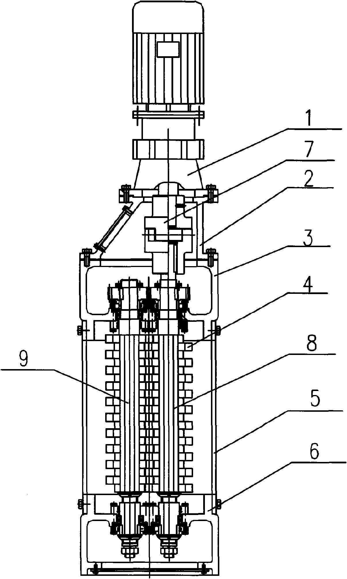
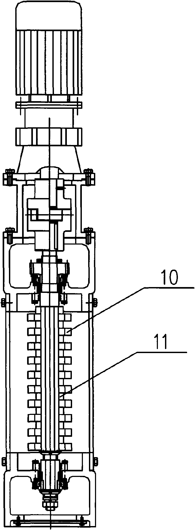
[0031] Such as Figure 1-Figure 3 As shown, the crushed grille of the present invention mainly includes a geared motor 1, a coupling box 2, a transmission shaft box 3, a guide bracket 5, and a tail box 6, from top to bottom, and each component is vertically installed in sequence. among them:

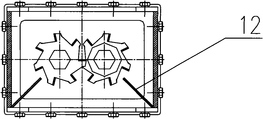
[0032] The output shaft of the reduction motor 1 is connected to the upper end of the driving shaft 8 through a coupling 7; the driven shaft 9 and the driving shaft 8 are arranged in parallel, and the upper and lower ends of the two are respectively supported by the transmission shaft box 3 and the tail box through bearings 6, and the middle part passes through the entire diversion bracket 5, the front and rear sides of the diversion bracket 5 have diversion openings, and the two sides of the diversion opening are provided with guide plates 12 inward. The driven shaft 9 and the driving shaft 8 are connected by a transmission mechanism, and the coupling-type tool assembly 4 is respectively ...


PUM


Abstract

The invention discloses a crush type grid which comprises a reduction motor, a coupler box, a transmission shaft box, a diversion bracket provided with a diversion port and a tail box, wherein the reduction motor, the coupling box, the transmission shaft box, the diversion bracket and the tail box are vertically installed from top to bottom; the output shaft of the reduction motor is connected with the upper end of a driving shaft through a coupling in the coupling box; a driven shaft is parallel to the driving shaft, the upper ends and the lower ends of the driving shaft and the driven shaftare respectively supported in the transmission shaft box and the tail box through bearings, the middle parts of the driving shaft and the driven shaft penetrate through the whole diversion bracket, the driven shaft is connected with the driving shaft through a transmission mechanism, coupling type cutter assemblies are respectively installed on the driving shaft and the driven shaft in a corresponding way in the diversion bracket. The invention can crush solid substances such as cloth strips, wood chips, empty glass jars and the like mixed in a sewer to prevent water treatment equipment of thesewer from being blocked, and ensure normal operation of the water treatment equipment. The equipment can be used by matching with a traditional pump station, and can be singly used, thereby changingan application form of the traditional pump station.

Description

Technical field [0001] The present invention is a device related to sewage treatment of sewers, in particular a crushing grid, that is, a grating with a grinder, and is mainly a device developed for crushing and processing solid waste mixed in the sewer. The equipment can crush solids such as cloth pieces, wood chips, empty bottles and cans mixed in the sewer to prevent the clogging of the sewer process equipment and ensure the normal operation of the sewer water treatment equipment. The equipment can be used in conjunction with the traditional pumping station or used alone, thus changing the application form of the traditional pumping station. Background technique [0002] China's water resources per capita are small and their spatial distribution is uneven. With the acceleration of urbanization and industrialization in China, the demand for water resources is also increasing. In this context, the sewage treatment industry has become an emerging industry, currently in the same...

Claims


Application Information

Patent Timeline
Patent Type & Authority Applications(China)
IPC IPC(8): B02C18/06B02C18/18E03F5/00
Inventor 沈枚华
Owner JIANGSU DATANG ENVIRONMENTAL PROTECTION ENG
Learn More