Electric water pump

A technology of electric water pump and water guide cover, applied in the direction of pumps, pump devices, pump components, etc., can solve the problems of unsmooth, unstable return of water tank fluid, and limited improvement of engine heat dissipation efficiency, so as to improve heat dissipation efficiency and improve use. Longevity, effect of reducing internal temperature

Inactive Publication Date: 2010-02-24
SHENZHEN YIBAO INDAL
View PDF0 Cites 5 Cited by
  • Summary
  • Abstract
  • Description
  • Claims
  • Application Information

AI Technical Summary

Problems solved by technology

However, when the above-mentioned heat dissipation design is actually used, when the internal chamber 100 is filled with water, because the water tank liquid enters and exits the internal chamber 100 through the perforation 111, it is easy to cause the backflow of the water tank liquid to be unstable and not smooth. , so that the heated water tank liquid in the inner chamber 100 is not easy to flow back into the water drawing space 101, and the relatively low temperature water tank liquid in the water drawing space 101 is not easy to re-enter the inner chamber 100, so that the electric water pump 1 cannot be effectively dissipated. Internal thermal energy, so that the overall temperature of the electric water pump 1 is still relatively high, causing the temperature of the water tank fluid pumped into the engine (not shown) to be relatively high, so the improvement of the heat dissipation efficiency of the engine is quite limited

Method used


Image

  • Electric water pump
  • Electric water pump
  • Electric water pump

Examples


Embodiment Construction

[0011] Below in conjunction with accompanying drawing and embodiment the present invention is described in detail:

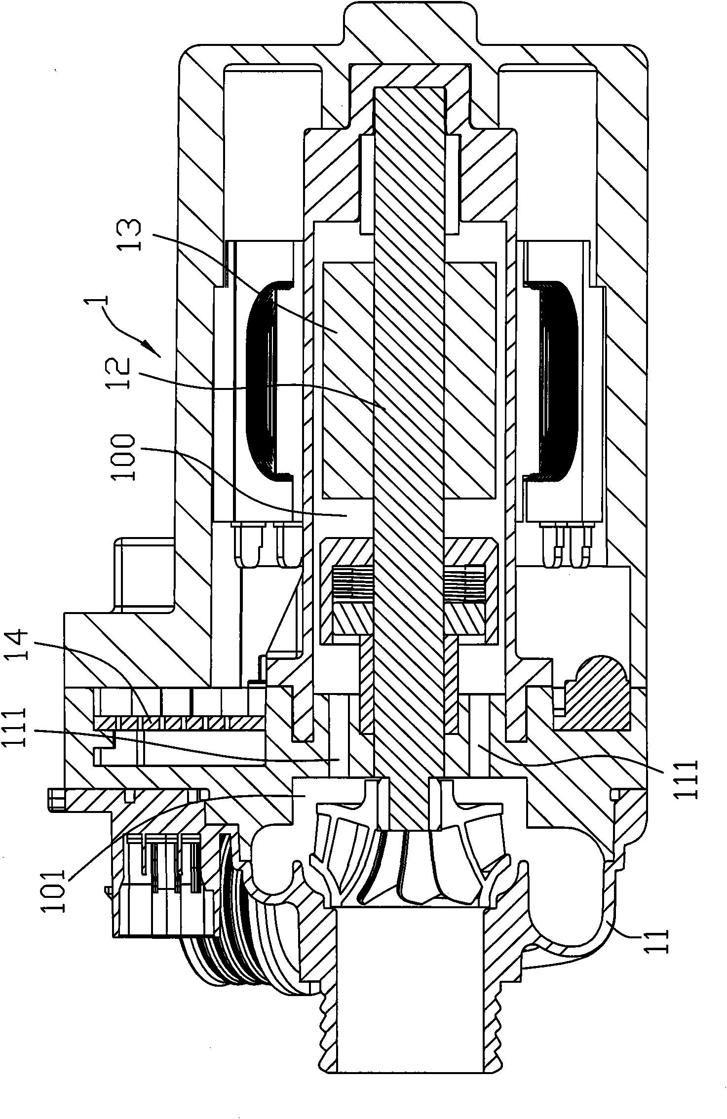
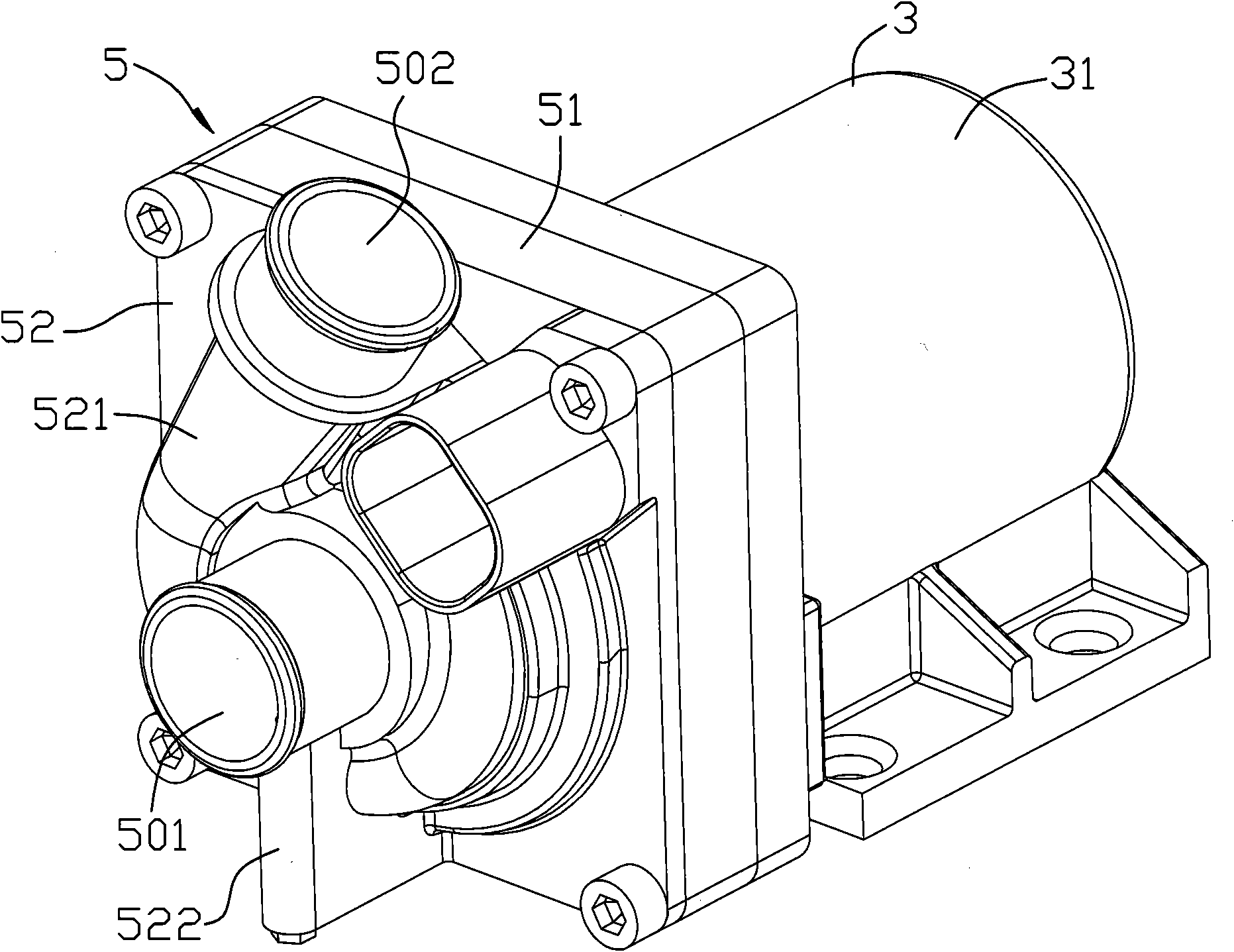
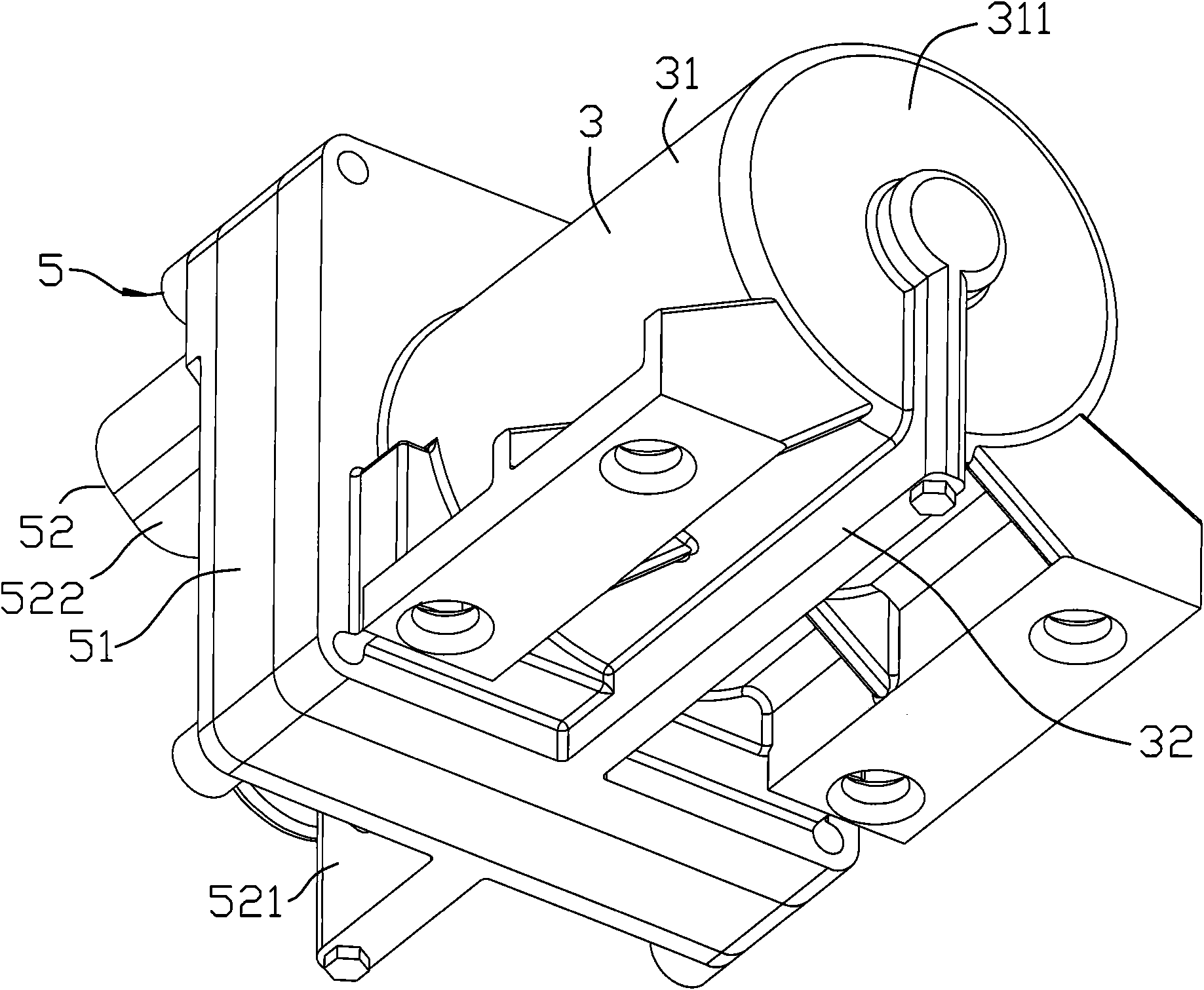
[0012] Such as Figure 2-4 As shown, the embodiment of the electric water pump of the present invention can be used to pump liquid into an engine (not shown) to assist in engine cooling. The electric water pump includes a hollow casing 3 with an opening facing forward, a hollow sleeve 4 installed and fixed in the casing 3 with an opening facing forward, and a hollow sleeve 4 installed and fixed between the casing 3 and the casing 4 to cover the casing 3 and the sleeve 4. The water guide cover 5 at the front end of the sleeve 4, and a water drawing mechanism 6 installed in the casing 3, the sleeve 4 and the water guide cover 5.

[0013] The casing 3 includes a hollow casing body 31 with an opening facing forward, and a communicating pipe body that protrudes from the outer peripheral surface of the casing body 31 and is bent and extended and fixed to the rear sid...


PUM


Abstract

The invention relates to an electric water pump comprising a casing, a sleeve barrel, a water guide cover and a water pumping mechanism. The casing comprises a communication pipe body which is convexly arranged at the peripheral face of a casing body in a mode of extending back and forth and is provided with a communication flow passage in a penetrating way, and the casing body is provided with athrough hole which is communicated with the back end of the communication flow passage. The sleeve barrel is provided with a communication hole which is communicated with the inside of the sleeve barrel and the through hole. The water guide cover is installed and fixed at the front ends of the casing and the sleeve barrel and is provided with a diversion hole which is communicated between a waterinlet of the water guide cover and the communication flow passage. The water pumping mechanism comprises a rotating shaft which is pivoted in the sleeve barrel and extends into a water pumping space,and the rotating shaft is provided with a heat-radiation flow passage which is communicated with the communication hole and the water pumping space in a penetrating way. By the structural design ofarranging the communication pipe body at the external surface of the casing body convexly, the internal temperature of the electric water pump can be effectively lowered, and the service life of the electric water pump and the heat-radiation efficiency of the electric water pump to an engine are relatively enhanced.

Description

technical field [0001] The invention relates to a water pump, in particular to an electric water pump. Background technique [0002] In a car, in order to reduce the engine operating temperature, an electric water pump in the cooling system pumps the water tank liquid into the cooling channel of the engine to dissipate the heat energy of the engine. However, during the operation of the electric water pump, both the stator and the internal control circuit will generate heat energy. Although the external heat energy of the stator can be conducted to the outside or transmitted by air convection to dissipate heat by itself, the internal heat energy of the stator will gradually accumulate, resulting in internal heat generation in the electric water pump. High temperature, in order to avoid failure of the electric water pump itself due to overheating, and cause the temperature of the water tank fluid pumped into the engine to be too high, resulting in low heat dissipation efficien...

Claims


Application Information

Patent Timeline
Patent Type & Authority Applications(China)
IPC IPC(8): F04D13/06F04D29/58
Inventor 邱进成陈世琦陈嘉佑黄昱畯
Owner SHENZHEN YIBAO INDAL
Why Eureka
Try Eureka