Generator local discharge on-line monitoring device and monitoring method thereof

A partial discharge and monitoring device technology, applied in the field of generator partial discharge on-line monitoring device, can solve problems such as single anti-interference means, low measurement bandwidth, and reduced sensitivity and reliability of measurement results, so as to achieve good anti-dry effect and improve reliability High safety and high effect

Inactive Publication Date: 2010-02-24
西安博源电气有限公司 +1
View PDF0 Cites 24 Cited by
  • Summary
  • Abstract
  • Description
  • Claims
  • Application Information

AI Technical Summary

Problems solved by technology

[0007] 2) The designed measurement bandwidth is generally relatively low, up to 30MHz
[0008] 3) The anti-jamming method is relatively simple
[0009] The neutral point of the generator alone is not an ideal monitoring point, because the high-frequency component has been seriously attenuated when the discharge pulse in the stator winding is transmitted to the neutr

Method used


Image

  • Generator local discharge on-line monitoring device and monitoring method thereof
  • Generator local discharge on-line monitoring device and monitoring method thereof
  • Generator local discharge on-line monitoring device and monitoring method thereof

Examples


Embodiment 1

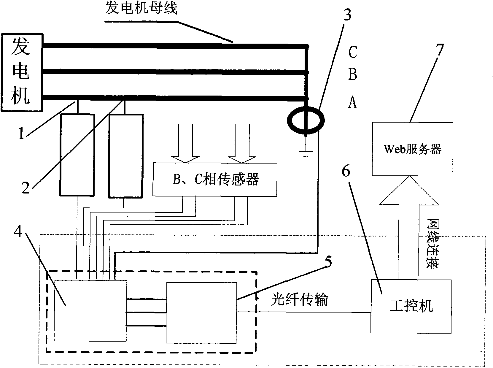
[0042] An online monitoring method for partial discharge of generators, including the following steps:

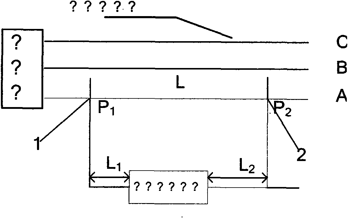
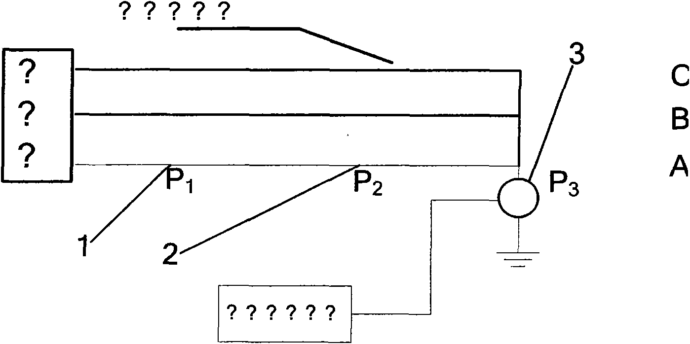
[0043] In the first step, a ceramic capacitance sensor 1 and a ceramic capacitance sensor 2 are installed on the generator bus. The ceramic capacitance sensor 1 is installed at the outlet end of the generator bus. The ceramic capacitance sensor 2 is installed in the same direction 15m away from the ceramic capacitance sensor 1. Place, while satisfying the formula

[0044] L 2 V a = L 1 V a + L V

[0045] Among them, the distance between the signal acquisition device and the ceramic capacitance sensor 1 is L 1 Is 35m, the distance between the signal acquisition device and the ceramic capacitance sensor 2 is L 2 Is 50m, the distance between ceramic capacitance sensor 1 and ceramic capacitance sensor 2 is 15m, V a Is the transmission speed of the signal in the cable, V is the transmission speed of the signal in the bus, and V is known a =0.8...

Embodiment 2

[0050] An online monitoring method for partial discharge of generators, including the following steps:

[0051] In the first step, a ceramic capacitance sensor 1 and a ceramic capacitance sensor 2 are installed on the generator bus. The ceramic capacitance sensor 1 is installed at the outlet end of the generator bus. The ceramic capacitance sensor 2 is installed in the same direction 8m away from the ceramic capacitance sensor 1. Place, while satisfying the formula

[0052] L 2 V a = L 1 V a + L V

[0053] Among them, the distance between the signal acquisition device and the ceramic capacitance sensor 1 is L 1 Is 25m, the distance between the signal acquisition device and the ceramic capacitance sensor 2 is L 2 Is 33m, the distance between ceramic capacitance sensor 1 and ceramic capacitance sensor 2 is 8m, V a Is the transmission speed of the signal in the cable, V is the transmission speed of the signal in the bus, and V is known a =0.8V,...


PUM


Abstract

A generator local discharge on-line monitoring device comprises a ceramic capacitive transducer 1, a ceramic capacitive transducer 2, and a high frequency transducer 3 which are connected with a signal conditioner unit 4, the signal conditioner unit 4 is connected with an acquisition card 5, the acquisition card 5 is output via optical fiber and is connected with a network card of an industrial personal computer (IPC) 6, and the IPC 6 is connected with a Web server 7. The monitoring method thereof comprises: taking a signal at location of a neutral point, dividing coupled signal into 1000 segments by the high frequency transducer 3, calculating the maximum value of each segment and the average value, taking the average value as signal dynamic threshold value, then comparing with the absolute value of the neutral point signal, eliminating if smaller than dynamic threshold value, otherwise, comparing again, judging as a discharge point if the polarities are identical, and judging as an interference signal if the polarities are opposite. The invention has the characteristics of good anti-interference effect, high security and easy and convenient application.

Description

[0001] Field [0002] The invention belongs to the field of on-line monitoring of power equipment insulation, and in particular relates to an on-line monitoring device for partial discharge of a generator and a monitoring method thereof. Background technique [0003] The partial discharge measurement system has been used for monitoring the insulation status of generator stator windings for more than 40 years. In the past 25 years, the further development of generator partial discharge online monitoring technology has gradually made it the most extensive and effective insulation state monitoring method after temperature monitoring. As of 2001, in North America, more than 50% of generators / motors operating above 20MW have installed partial discharge online monitoring systems for insulation diagnosis. The reason why people pay so much attention to partial discharge monitoring is that partial discharge will damage the stator winding insulation. After the operation department has orga...

Claims


Application Information

Patent Timeline
IPC IPC(8): G01R31/34G01R31/06
Inventor 任战国梁红军徐阳席保锋王长安易冉杨文虎
Owner 西安博源电气有限公司
Why Eureka
Try Eureka