Optical scanner for image forming apparatus

一种光扫描装置、图像的技术,应用在应用电荷图形的电记录工艺、应用电荷图形的电记录工艺的设备、光学等方向,能够解决图像偏移、图像质量下降、反射光光路偏移等问题,达到抑制光路偏移、抑制位置偏移、抑制热变形的效果

Inactive Publication Date: 2010-02-24
KYOCERA DOCUMENT SOLUTIONS INC
View PDF1 Cites 3 Cited by
  • Summary
  • Abstract
  • Description
  • Claims
  • Application Information

AI Technical Summary

Problems solved by technology

Therefore, when the member supporting the mirror is thermally deformed, the optical path of the reflected light is shifted, and the optical scanning device may not function normally.
[0006] For example, when the supporting member supporting the light guide mirror is thermally deformed and the optical path of the light reflected by the light guide mirror deviates, the laser light cannot be correctly incident on the light receiving element of the substrate, so it is difficult to accurately Controls where the image is written on the photosensitive drum
As a result, the position on the photosensitive drum after the image is written deviates from the original position, so-called image shift occurs, and the image quality deteriorates.

Method used


Image

  • Optical scanner for image forming apparatus
  • Optical scanner for image forming apparatus
  • Optical scanner for image forming apparatus

Examples


Embodiment Construction

[0032] Embodiments of the present invention will be described below with reference to the drawings.

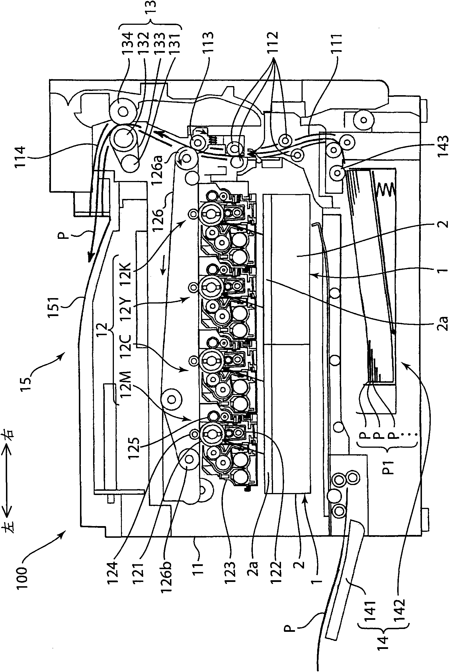
[0033] First refer to figure 1 , the overall structure of the printer 100 according to one embodiment of the present invention will be described.

[0034] like figure 1 As shown, the printer 100 of this embodiment is provided in the main body 11 of the apparatus: an image forming unit 12 for forming an image and transferring the image to paper P; and a fixing unit 13 for fixing the image transferred to the paper P. processing; and the paper storage unit 14 storing paper P for image formation. In addition, a paper discharge unit 15 for discharging the paper P after fixing processing to the upper part of the device main body 11 is also provided in the device main body 11 . The printer 100 is constituted by arranging the structural units shown above.

[0035] The image forming unit 12 forms a toner image on the paper P supplied from the paper storage unit 14 . In this embodi...


PUM


Abstract

An optical scanner for an image forming apparatus has a housing having a wall surface provided with a through-hole, and an optical scanning unit, which is provided within the housing, scans light on an object to be scanned in order to form an image on the object to be scanned, and includes: a polygon motor; a polygon mirror that reflects the light while being rotated by a driving force of the polygon motor; a mirror member that reflects the light reflected by the polygon mirror, toward a target object; and a mirror holding member that is attached to the wall surface of the housing and holds the mirror member. The mirror holding member has a heat radiation part that is exposed to the outside of the housing through the through-hole. Thereby, heat radiation of the mirror holding member is prevented, and position shift of the mirror holding member caused by the heat radiation is prevented, and then the optical scanner can proceed normal function.

Description

technical field [0001] The present invention relates to an optical scanning device of an image forming device. Background technique [0002] Conventionally, an image forming apparatus such as a printer has an optical scanning unit (LSU: Laser Scanning Unit) for writing an electrostatic latent image (image) on a photosensitive drum (object to be scanned) (refer to Japanese Patent Laid-Open Publication 2002- 328321). [0003] Such an optical scanning device has in a housing: a light source for emitting laser light; a polygonal mirror for reflecting laser light emitted from the light source while rotating; a polygonal mirror motor for driving the polygonal mirror to rotate; and an optical system for turning the polygonal mirror The laser light reflected by the multi-faceted mirror is guided to the lens and mirror on the photosensitive drum. Then, the laser light reflected by the polygon mirror is guided onto the photosensitive drum through the optical system, and the photosen...

Claims


Application Information

Patent Timeline
Patent Type & Authority Applications(China)
IPC IPC(8): G02B26/12
CPCG03G15/326G02B26/121G03G15/0435
Inventor 冨冈宏行
Owner KYOCERA DOCUMENT SOLUTIONS INC
Why Eureka
Try Eureka